
eng. Cz. Klimczewski, "A 20 Watt amplifier powered from the mains"
Radio dla Techników i Amatorów 1946/06
At the request of our readers, we provide a schematic and assembly diagram with a description of the low frequency power amplifier. This amplifier can be used to power 2 watts or more speakers with less power. For the amplifier to work properly and without distortion, the sum of power consumed by these speakers can not exceed 20 watts. This amplifier, thanks to various possibilities, is used for sounding squares, slides, stands, railway stations, gardens, etc. It has five inputs, to which we connect depending on the circumstances.
We can strengthen live speech and music, including appropriate "capacitive microphone" or "carbon" terminals. We can amplify music from gramophone records, including the amplifier "adapter" as well as broadcasts from radio receivers and various types of transmissions given over the telephone line. In order to facilitate assembly outside the schematic diagram, we give assembly diagrams as well as a photograph of the amplifier made and a brief description of its work.
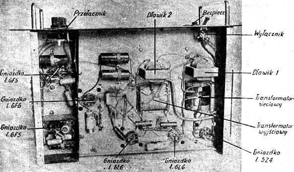
Zdjęcie wzmacniacza od dołu
Our amplifier consists of a total of 5 amplifying and 1 rectifying tubes. The first three tubes work in a low-frequency resistive-capacitive system, the first of which is used to amplify the transmitted signals from a condenser microphone or from another installed far from the amplifier, resulting in the weakening of the signal. After reinforcement in the first member on the anode of the 6F5 tube, it is directed to a two-stage low-frequency resistive-capacitive amplifier operating on 6F5 and 6F6 tubes, and then on a power amplifier in the push-pull mode in the AB1 class. Coupling the power amplifier with the last low frequency is transformer. The power amplifier works on two 6L6 tubes. The output is also transformer and adapted for different voltages, i.e. for different types of loudspeakers and different operating conditions. If the speakers work in parallel, they should be connected so that the appropriate speaker terminals are connected to the appropriate terminals of the output transformer, that is, to keep them matching the amplifier's operation. Each loudspeaker with more power has a transformer, on which there are terminals for proper connection.
In the case of amplification from the adapter, from the receiver line or carbon microphone (connected by a suitable transformer, which together with the battery is usually assembled together with the microphone), we give the entrance to the second 6F5 tube by switching the switch accordingly. Signals, which in this case are stronger, are enough to drive this tube, and thus the whole amplifier. To adjust the volume of the voice we use in the mesh of the second tube a log potentiometer with a resistance of 0.5M connected by a solid capacitor with a capacity of 40,000pF to the grid of the second tube 6F5 and its leakage resistance of 0.5M. The values of the parts used to build the amplifier are selected so that the amplifier works purely without distortion, and releases the maximum power. The receiver is powered by AC power. For this purpose, a rectifier consisting of a mains transformer adapted for 120 and 220 volts, a 5Z4 rectifier tube and a filter for smoothing the pulsating DC voltage was built in. The volume of the alternating current's hum depends on the kindness of the filter.
Technical data of chokes and transformers in our amplifier are given below for easier execution. The kind of work of an amplifier depends on the kindness of their performance. It should be remembered that the dimensions of the core can not be smaller than those given. The core plates must be firmly compressed so that they do not "play" during operation. Transformer windings must also be strongly wound and the layers must be insulated from each other. Capacities of electrolytic capacitors in the filter smoothing the voltage may be higher, never lower, but it must be remembered that the operating voltage, like punctures, can not be lower than 450/500 volts, because you can expose them to fast damage, especially the first one after the rectifier tube when the voltage is turned on. To check if the amplifier is upstream, a control lamp placed in the amplifier's lighting circuit is used.
Amplifier type 25AS
From the assembly drawings, photographs and detailed description of the parts used for the construction of the amplifier, the interested Readers will get to know exactly how to assemble the equipment used and the connections between them. American type tubes have been used for the amplifier, due to the ease of their purchase, and at a lower cost compared to those commonly used in radio receivers.
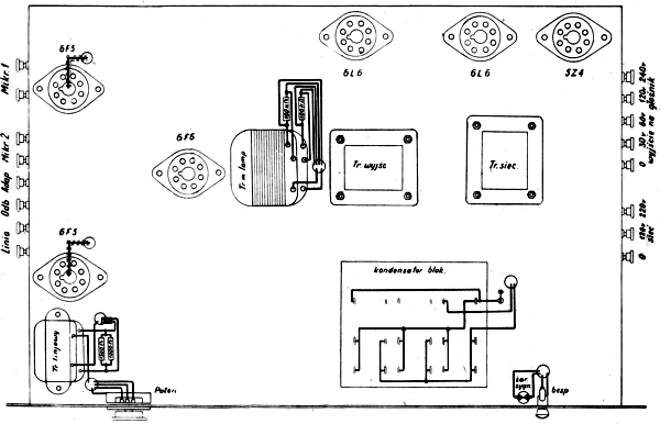
View of the chassis from the top
View of the chassis from the bottom
Parts list and technical data
|
Transformer type |
Core cross section in mm |
Primary winding |
Secondary winding |
Wire diameter in mm |
|
Mains |
35x50 |
410turns |
- |
0,6 |
|
Output |
35x35 |
2x1780turns |
- |
0,2 |
|
Interstage |
35x45 |
4500turns |
- |
0,15 |
|
Linear (telephone line) |
17x18 |
3000turns |
- |
0,15 |
|
Choke I - 10H |
17x18 |
4000turns |
- |
0,2 |
|
Choke II - 20H |
17x18 |
10000turns |
- |
0,1 |
The air gap in the given chokes is 0.1mm.
Resistors:
- 70/1W - 2;
- 125/8W - 1;
- 600/1W - 1;
- 1K/1W - 1;
- 2K/1W - 2;
- 50K/1W - 7;
- 100K/0,5W - 4;
- 200K/1W - 3;
- 500K/1W - 2;
- 1M - 1,
Potentiometer: 1M - 1.
Capoacitors:
- 400pF/250/750V - 1;
- 10000pF/500/5000V - 3;
- 40000pF/150/450V - 4;
- 4µF/350/385V - 2;
- 6µF/350/1250V - 1;
- 8µF/350/385V - 1;
- 10µF/63/70V - 2;
- 12µF/350/1250V - 1;
- 25µF/6/8 - 2.
Tubes: "american" types; 6F5 - 2; 6F6 - 1; 6L6 - 2; 5Z4 - 1.
Indicator 6V/0,04A - 1.
Radio tube caps (2 pcs), bipolar circuit breaker (1pc), radio tube holders (6pc), bulb holder (1pc), recessed fuse holder (1pc), red signal glass socket (1pc), contact clips for entry and exit (16 pcs), ladders with 4 terminals (5 pcs), ladder with 1 end (1 piece), Philips pattern dial switch (1 piece), chassis 6x29x42cm, small assembly material.
Dimensions of the amplifier: 22x29x42cm.
To avoid interference from the network to the amplifier, use 5000pF / 500 / 3000V - 2pc and 10000pF / 500 / 3000V capacitors - 1pc.
")
")
")
")
")