
Radio engineering time travel (1927)
I invite you to look at the "pictures" related to radio technology. They come from various sources. The gallery has its sister version in Polish and Russian. Versions in other languages will be added successively. More detailed descriptions can be found in other language versions (articles are related and can be displayed by clicking on the icons with flags on the left, top of the TRIODA website). Of course, I will complement translations of signatures quite slowly. All descriptions are displayed using the present tense and not the past - this is not a mistake only deliberate action - a reference to the original descriptions from those years. In order not to delay the possibility of viewing the gallery, this site is made available as a "site under construction" - for which I apologize to all guests. At the beginning and end of each set of photographs there are links allowing to change the period - calendar year.
[Previous period] [Next period]
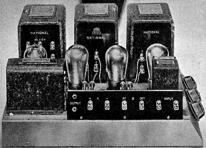
NATIONAL Power Amplifier.
Makes your present Radio Set the last word in Fidelity of Reproduction and supplies all B and C current from the lamp socket. Designed on sound engineering principles in collaboration with Arthur H. Lynch and James Millen, it combines a B Power-Supply and complete audio amplifier of the highest type. It is made to use either the Raytheon BH or Rectron Rectifying Tube. Each unit is newly designed for heavy and continuous duty, built to established NATIONAL standards.
(Radio for January, 1927)
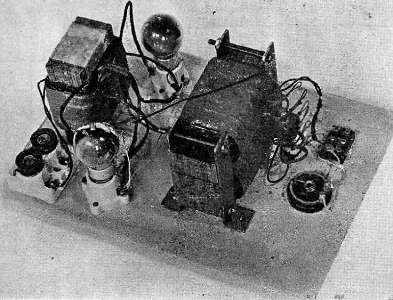
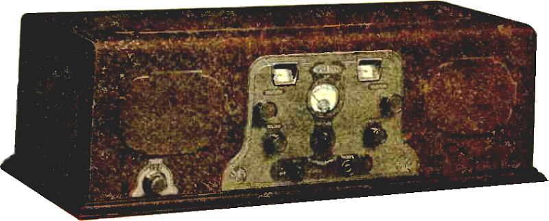
Complete "A" Eliminator.
Article: A Home-Built "A" Battery Eliminator For Supplying 2 Amperes of Rectified Filtered Current at 6 Volts Without the Use of A Battery.
"Almost all of the devices hitherto described for the complete replacement of the A battery by a.c. socket power have required that the tube filaments be wired in series. While this enables the use of a rectifier of limited current capacity, it has introduced several complications and limitations that are not found when the filaments are connected in parallel. Consequently there is a demand for a power system to supply at least 2 amperes at 6 volts directly from a 110 volt alternating current line..."
(Radio for January, 1927)
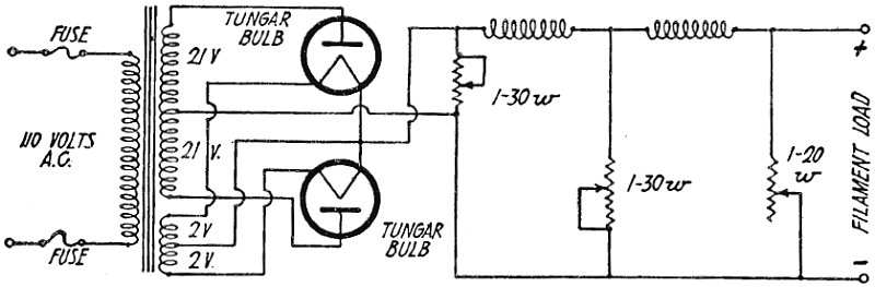
Wiring Diagram for Complete "A" Unit, Using Resistances in Filter.
(Radio for January, 1927)

Model of Double Beam Radio Beacon for Guiding Aircraft.
Article: The Double Beam Radio Beacon As Developed for the Guidance of Aircraft.
"A model of a miniature airplane guided by radio signals from a miniature transmitting station is on exhibit in the radio laboratory of the Bureau of Standards to illustrate the application of the double beam radio beacon to the navigation of flying machines through darkness, fog, or other adverse weather conditions. As you turn a switch, plug in the headphones, and move the plane slightly to the right or left, there is a difference in the intensity and characteristics of the emitted radio signal. But as long as the plane remains on the center line of the box, the signals are uniform..."
(Radio for January, 1927)
Rear View of Three-Tube Experimental Set.
Article: A Stabilized High Gain Regenerative Receiver. Suggestions for Preventing Oscillations Which Should Interest Every Experimenter.
"The receiver described herein is the result of considerable experimenting with reflex and regenerative receivers. The main objection to various types of regenerative receivers is that they oscillate and so bloop the whole neighborhood. Generally the regeneration control is used so that the detector is on the verge of oscillation, or even oscillating for 'zero beat' reception. Usually the novice, or practically everyone using a regenerative receiver, will tune for distant stations with the set oscillating so as to pick up the carrier wave and then try to 'back' it down from that point in order to make the music or speech intelligible. Everyone knows how those nice little whistles caused by one or several of these receivers kill all chance of any dx for anyone else in town..."
(Radio for January, 1927)
Circuit Diagram of Stabilized Regenerative Receiver.
(Radio for January, 1927)
Rear View of Completed Receiver.
Article: The Simplicity Receiver. An Easily Built, Single -Control Four Tube Set.
"The excellent results secured with the L-C circuit, first introduced in October, 1925 RADIO, have created interest in the possibility of assembling the set with ready-made instead of home-made coils. This circuit, which was originated by Dr. Hull of the Bell Telephone Laboratories, is now arranged for single control in tuning local stations. It compares most favorably with any four-tube set as to selectivity, sensitivity and tone quality..."
(Radio for January, 1927)
Arrangement of Sub-Base Apparatus, With Panel Drilling Instructions.
(Radio for January, 1027)
Schematic Wiring Diagram of Simplicity Receiver.
(Radio for January, 1027)
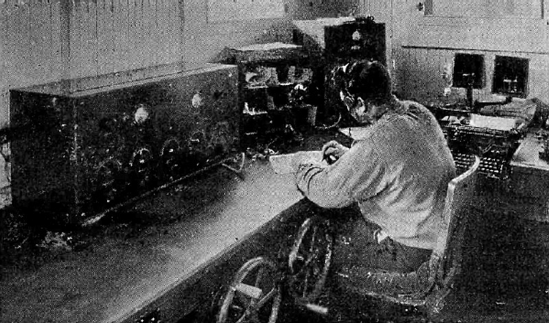
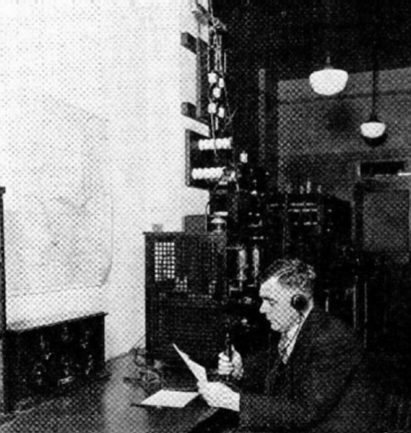
Short and Long Wave Telegraph Receiving Sets and Transmitter Control at WBZ
(Radio for January, 1927)
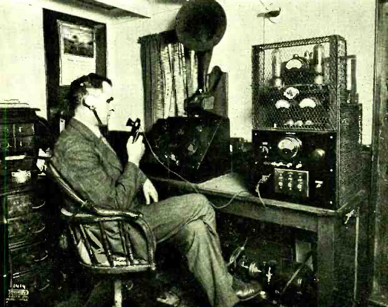
Completed Short Wave Receiver.
Article: A Short Wave Receiver for the B. C. L.
"The increasing number of kits and circuits for reception in the waveband from 20 to 150 meters is a good indication of the interest shown by the B.C.L. in the work being done by the amateur, as a large number of these kits are undoubtedly going into the hands of the broadcast fan. With several stations broadcasting good programs on wavelengths below 100 meters, the B.C.L. who cannot understand the code can still have his fun with long distance, short wave reception. Most of the circuits shown in past issues of RADIO have included the short wave tuner, a detector and one stage of audio frequency amplification. As most B.C.L. readers already have at least a two stage audio amplifier, or its equivalent, they are particularly interested in a tuner and detector unit which can be connected to their present audio amplifier with a minimum of complications..."
(Radio for January, 1927)
(Radio for January, 1927)
Television Projector.
Article: Radio Photography and Television. A Brief Survey of Some Recent Developments and Future Possibilities.
"In the well known play by George Bernard Shaw, 'Back To Methuselah' is described a scene which is supposed to take place in the year 2170. The head of the British Government holds conferences with his various cabinet ministers several hundred miles away. At his desk is a switchboard and in the background of the room is a silver screen. When he selects the right key at the switchboard a life sized image is flashed on the screen of the person with whom he is speaking at the same time as he hears the voice..."
(Radio for February, 1927)
The "MO" Four-Electrode Tube.
Article: A Four-Electrode Tube and Circuit. R. F. Amplification, Detection, and A. F. Amplification with One Vacuum Tube
"Four-electrode tubes and their associated circuits do not seem to have found much favor with radio experimenters. It is hard to account for this, as the results are quite worthy of experimentation and compare favorably with those obtained with the more popular three electrode tube. Different types of four electrode tubes have been evolved by inventors, some with two grids, and some with three anodes in addition to the cathode or filament. In each case it has been the aim of the inventor to obtain more work from the energetic electron stream from the filament as compared with that from the cathode of a three element tube..."
(Radio for February, 1927)
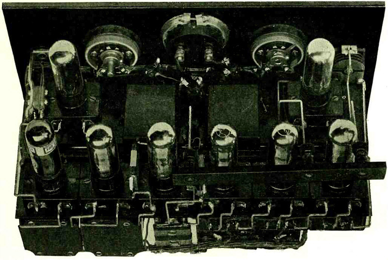
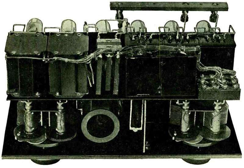
Power Amplifier Assembly.
Article: How to Build an Electric Phonograph. Complete Details for Construction of Power Amplifier and Battery Eliminator To be Used with Electric Pick-Up Device.
"Any old style phonograph can be easily and cheaply converted into a satisfactory electrical instrument by substituting an electromagnetic pick-up device, audio amplifier, and cone type loud speaker for the mechanical pick-up and tone chamber of the old instrument. These, combined with a socket power unit for supplying A, B and C voltages, are shown in the circuit diagram of Fig. 1 and accompanying pictures. To be completely electrical in operation the phonograph should have a motor-driven turn table..."
(Radio for February, 1927)
(Radio for March, 1927)
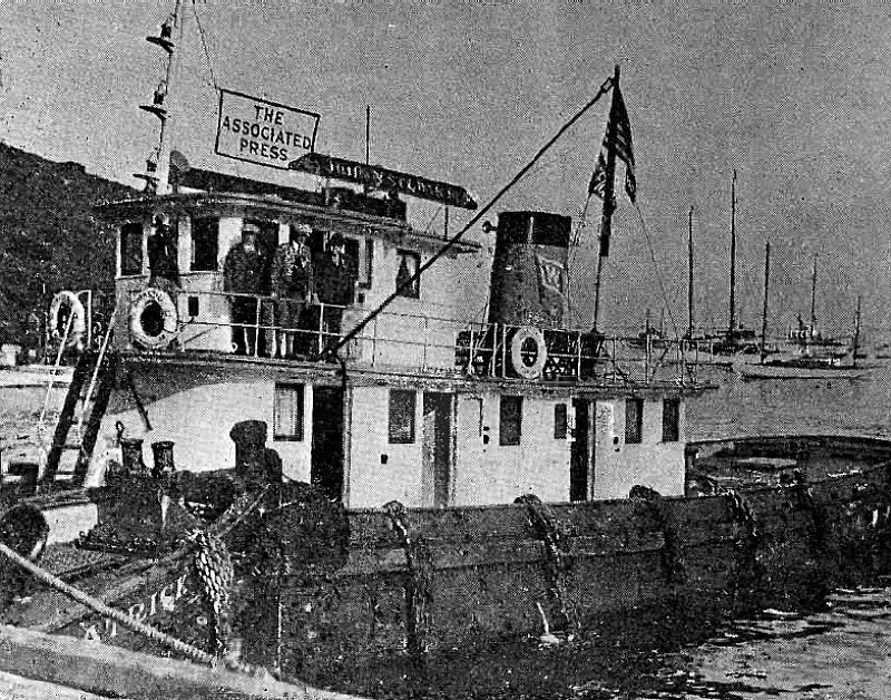
The News Transmitting Station.
Article: How Amateur Radio Scooped. A Thrilling Narrative of Success in Reporting the Catalina Swimming Contest.
"At the crack of the gun which started 102 swimmers in the famous Wrigley marathon swim at Catalina Island, it was amateur radio which first carried the news. The information on the arrangement of the starters had already been sent. So when that small batch of code '11.21' was transmitted from the Associated Press tug John H. Stewart, all of the newspapers in the United States knew about it within a minute. From then on, it was the trained news gathering force of the Los Angeles A. P. bureau who kept the air hot with the first news about the progress of the swim..."
(Radio for March, 1927)
The News Receiving Station.
(Radio for March, 1927)
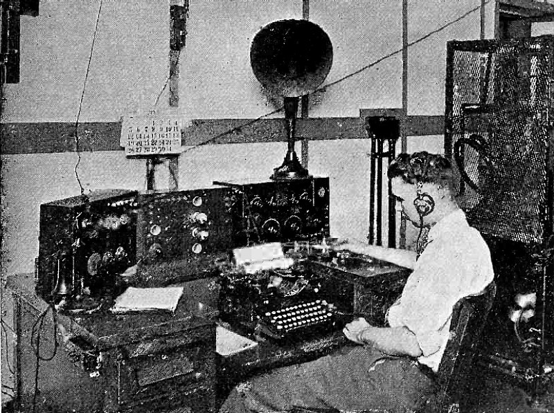
Measuring Input Transformer Characteristics.
Article: What Price Tone Quality? Improvements in Broadcast Transmitters Whereby the Complete Audio Scale May be Heard.
"The great improvement in tone quality since the Western Electric Company sold its first broadcast transmitter to the Detroit News five years ago has been made possible by patient research work in the Bell Telephone Laboratories. Today the audio output of a modern station covers a greater range of frequencies than the average set is able to receive efficiently. Of the several factors that have contributed to this result the most important is the audio input transformer..."
(Radio for March, 1927)
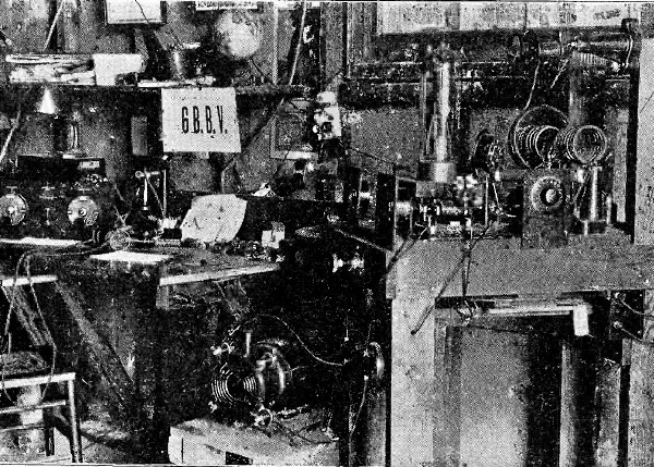
Radio Station 6BBV.
"Radio station 6BBV is owned and operated by Jack Baisby at 1010 Bates Ave., Hollywood, Calif. The transmitter is a 250 watt W.E. tube in a coupled Hartley circuit. An advance sync. gives 2200 volts on the plate, a home-made transformer 14.3 volts on the filament. With 370 mills on the plate and 50 on the grid 4.5 amps. are put in the antenna..."
(Radio for March, 1927)
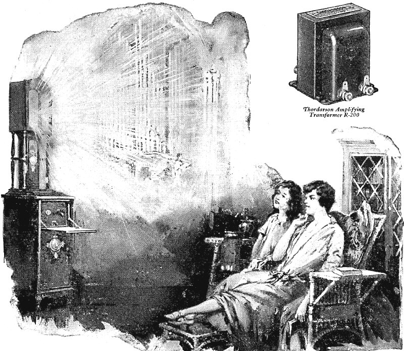
Advertisement
"Within your set slumbers a world of music which you can charm to a living fullness and richness of tone by installing Thordarson Amplification."
(Radio for March, 1927)
Advertisement
(Radio for March, 1927)
Advertisement
(Radio for March, 1927)
500 Watt Arc Transmitter at Pearl Harbor, T. H.
Article: The Passing of A Pioneer. Some Recollections of Wireless Before It Was Radio
"The dismantlement of KFS, the Beach Station at San Francisco, marks the passing of a pioneer at the advanced radio age of seventeen years. The mighty towers which stood near the Golden Gate as guards of the Pacific, were felled late in January of this year and every vestige of the station is gone from the site. Thus progress and the demands for residential expansion take their toll..."
(Radio for April, 1927)
Federal Telegraph Receiving Station at Daly City, San Francisco, 1927.
Article: The Passing of A Pioneer. Some Recollections of Wireless Before It Was Radio
(Radio for April, 1927)
The New KFS Operating Room at Daly City.
Article: The Passing of A Pioneer. Some Recollections of Wireless Before It Was Radio
(Radio for April, 1927)
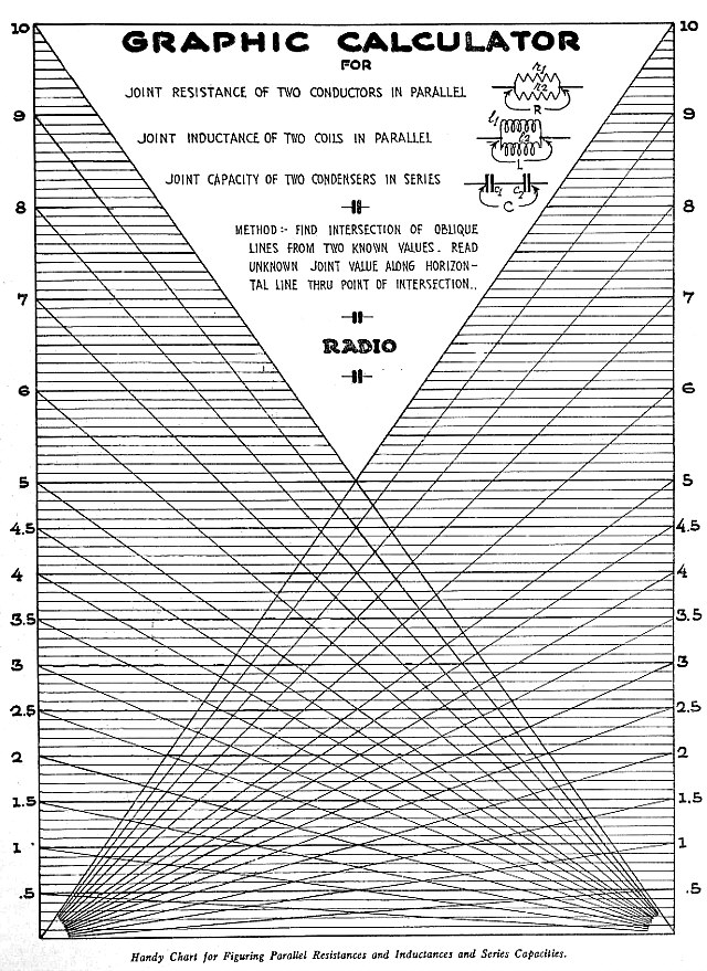
Handy Chart for Figuring Parallel Resistances and Inductances and Series Capacities.
(Radio for April, 1927)
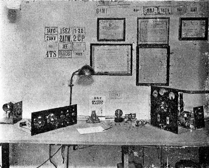
Radio Station 3AIY.
"Radio station Nu3AIY started in April, 1924, with the usual UV-201 and then in steps grew up to the present 50 watter. The station is owned by Charles Hackenyos, Jr., and is operated almost every evening after the usual quiet hours, as the transmitter creates quite a lot of QRM around the neighborhood. The only wave length used is 81 meters..."
(Radio for April, 1927)
Advertisement
(Radio for April, 1927)
Radiophone Equipment in the Vancouver Merchants' Exchange Building.
Article: The British Columbia Radiophone Service. Whereby Commercial Communication is Maintained with Forty Log Tow Tugs and Isolated Canneries.
"... 'Get me the tug Sea Lion' its owner told the radiophone operator in the Merchants' Exchange Building at Vancouver. And from the other side of the counter the operator put his headphones on and spoke into the microphone, 'Vancouver calling the Sea Lion.' The tug was sixty miles away, towing a long line of logs, some 800,000 board feet in all. After three repetitions of his call the operator heard in his headset: 'This is the Sea Lion calling Vancouver. Have you any orders ?' 'Yes,' replied Vancouver. 'You are to proceed direct to Station Two instead of Vancouver. Is all well on board ?' To which the Sea Lion came back with an '0. K., got your message. All well here. Sea Lion speaking,' and signed off. The owner of the line of tugs to which the Sea Lion belonged, walked back to his office a few doors away in the same building. He had sent a message which saved him hundreds of dollars in time and actual cash, since he was thus able to deliver his goods before his competitor and get a better price for them..."
(Radio for May, 1927)
Radiophone Equipment in "Sea Lion" Captain's Cabin.
Article: The British Columbia Radiophone Service. Whereby Commercial Communication is Maintained with Forty Log Tow Tugs and Isolated Canneries.
(Radio for May, 1927)
Rear View of Reciver.
Article: A Compact Portable Superheterodyne. Directions Whereby An Experienced Constructor Can Assemble An Eight Tube Set in Exceedingly Small Space.
"For vacation use, the ideal set is a really portable superheterodyne with a collapsible loop antenna, such as is here illustrated and described. The set is carried in one case and the batteries in another, connections being made by plugs and jacks which fit together when the set is placed on top of the battery case. The unusually compact arrangement of the parts requires that shielding be used to insure the fine tone quality and sensitivity of which the set is capable. Consequently its assembly is not a job for the novice and should be undertaken only by an experienced constructor able to read a circuit diagram without a pictorial wiring diagram..."
(Radio for May, 1927)
Bottom View, Showing Oscillator Compartment.
Article: A Compact Portable Superheterodyne. Directions Whereby An Experienced Constructor Can Assemble An Eight Tube Set in Exceedingly Small Space.
(Radio for May, 1927)
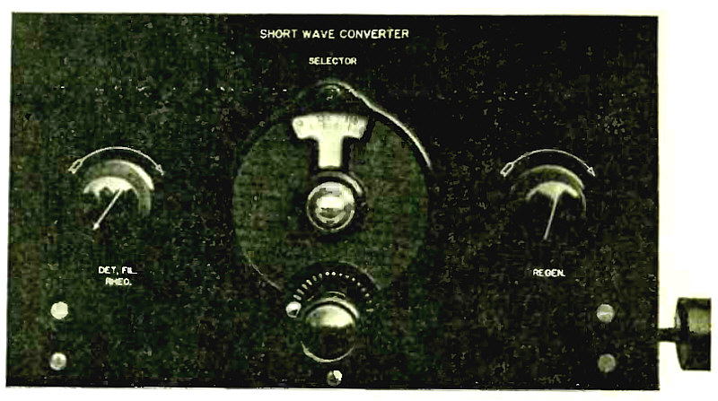
Panel View of Short Wave Converter.
Article: Short Wave Converter. Directions for Building a Simple and Easily Operated Tuner Enabling any Broadcast Receiver to Get the Short Waves.
"For those who wish to explore the short wave band from 15 to 125 meters, several ways are provided. However, most of them require changing the connections of the present broadcast receiver over to the short wave set. This arrangement has many drawbacks as all of the family may not be contented to listen to the short wave reception. By the time the receiver is restored to normal, the program you most desired has stopped. But any set may be converted instantly, and at will, into a short wave receiver by the use of the short wave converter herein described..."
(Radio for May, 1927)
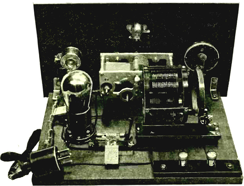
Rear View of Short Wave Converter.
Article: Short Wave Converter. Directions for Building a Simple and Easily Operated Tuner Enabling any Broadcast Receiver to Get the Short Waves.
(Radio for May, 1927)
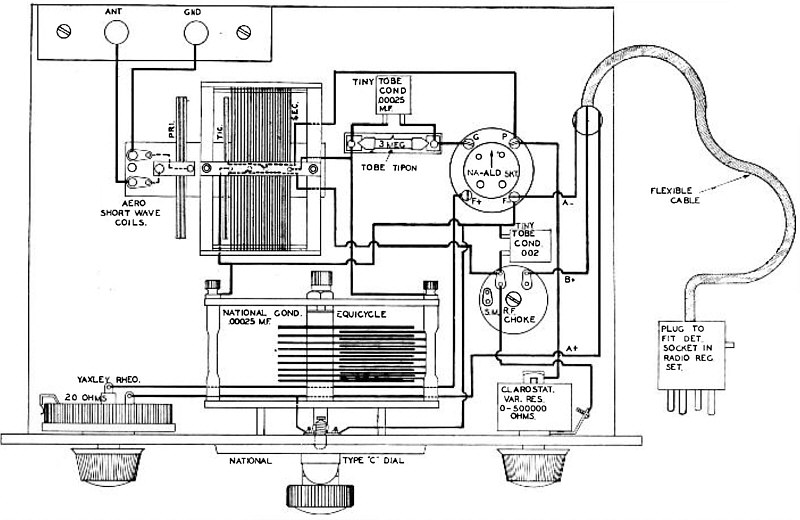
Pictorial Wiring Diagram of Short Wave Converter.
Article: Short Wave Converter. Directions for Building a Simple and Easily Operated Tuner Enabling any Broadcast Receiver to Get the Short Waves.
(Radio for May, 1927)
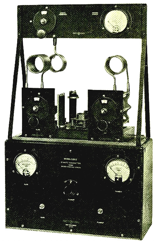
The Bumblebee Transmitter.
Article: The Bumblebee A 15 -Watt Short Wave Transmitter.
"A tuned-grid, tuned-plate transmitter using two 7.5 watt tubes has been developed by Ralph M. Heintz, 6XBB and 6GK. The power panel cabinet supports the antenna tuned circuit and the oscillator, which is mounted on a movable chassis..."
(Radio for May, 1927)
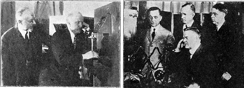
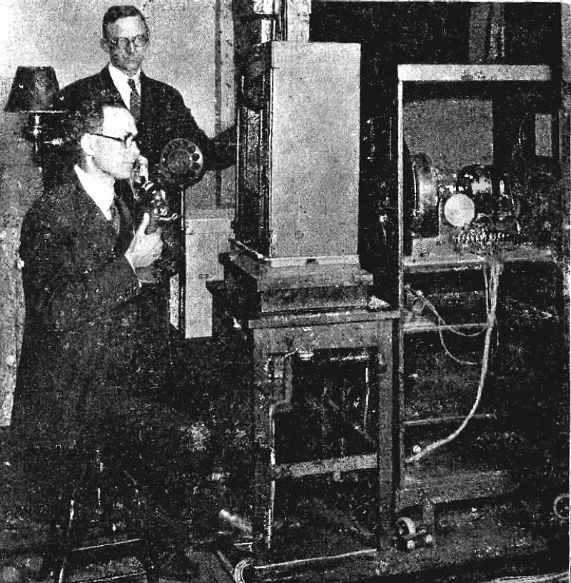
President Gifford Simultaneously Seeing and Hearing Hoover (left) / Secretary Hoover Being "Tele -Photographed" As He Telephones (right).
Article: Progress in Television. A Brief Review of Recent Developments and Future Probabilities by Arthur Hobart.
"Television has been humanity's dream since man first realized that interesting events were happening beyond the limits of his normal sight. Many a fairy tale was built around this theme. And now science is gradually making it a reality. First came the telescope to enlarge the visible and reveal the otherwise invisible in space. Then came photography to give permanent record that could be subsequently viewed at a distance. Next the telephone wires were used to transmit photographs and thereafter the radio was employed for the same purpose. And now both are being used to gain instantaneous view of motion in distant places..."
(Radio for June, 1927)
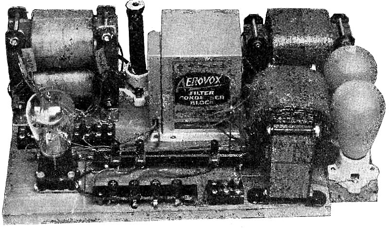
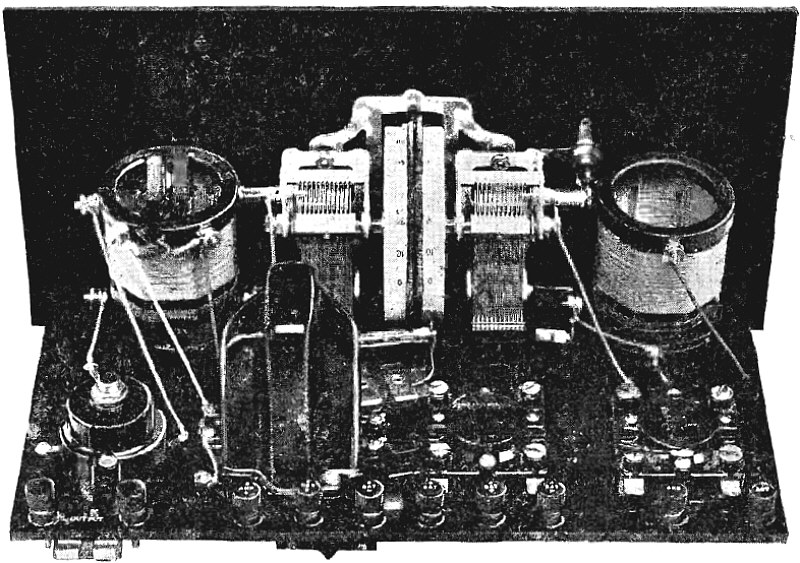
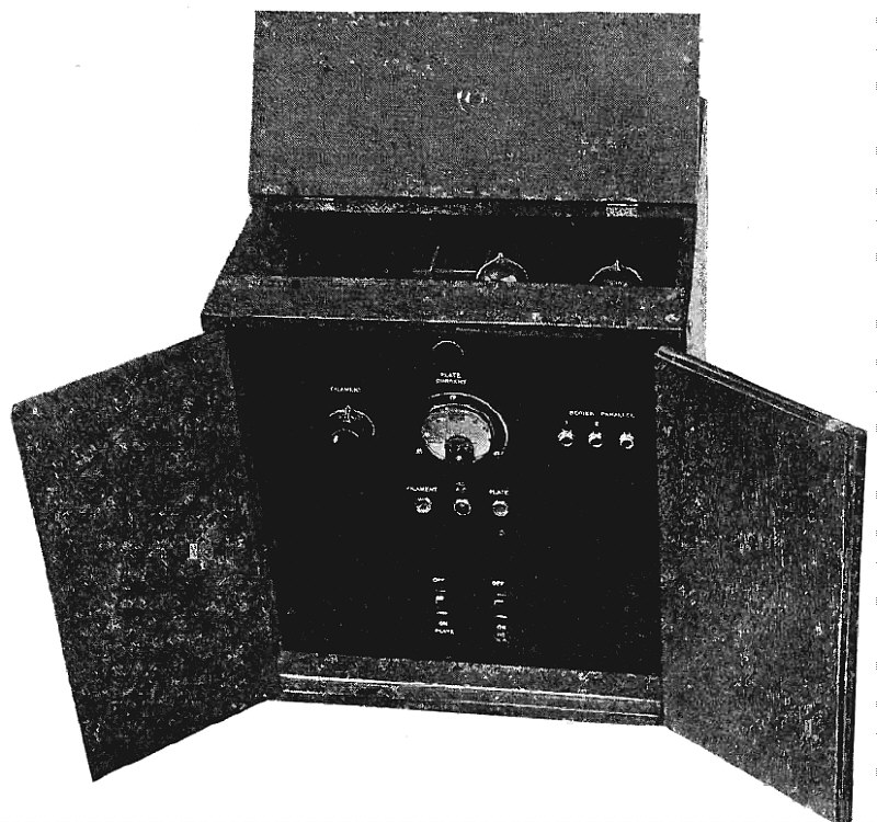
Experimental Model of ABC Eliminator Using the New Rectifier Tube.
Article: A New "ABC" Socket Power For Rectifying Alternating Current as The Filament, Plate and Grid Supply to Series-Connected 5-Volt Tubes.
"The first constructional data on a complete A, B and C battery eliminator for use with standard types of broadcast receivers appeared in the December, 1925 issue of RADIO. Since that time rapid progress has been made in the design of suitable rectifier and filter circuits, as well as the apparatus with which to build the eliminator.
The original arrangement comprised a two element, filament type rectifier supplying 80 milliamperes at about 150 volts, which limited its use to tubes of the 60 milliampere type, such as the CX-299, except the power tube, whose filament was lighted from alternating current through a step-down transformer. For new receiving sets this arrangement was very satisfactory, since apparatus especially designed for the '99 tubes could be installed. But where the set was already designed for the 6 volt tubes operated in parallel, the '99 tubes would not function as well as was desirable, usually due to the greater number of turns they require for radio frequency transformer primary windings..."
(Radio for June, 1927)
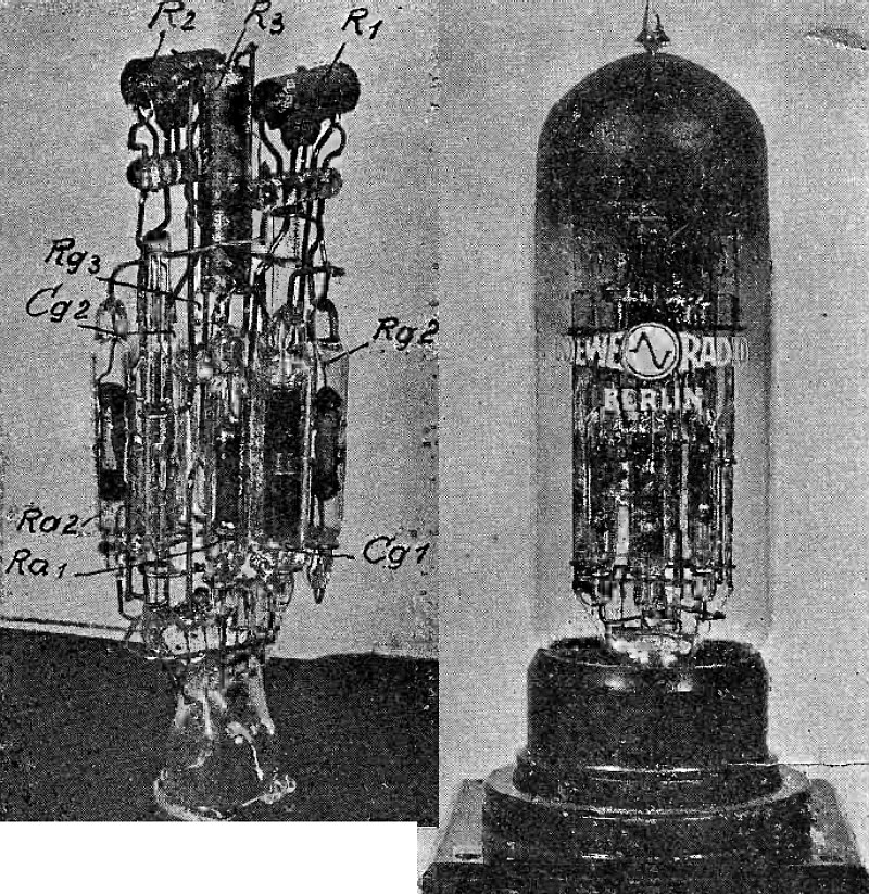
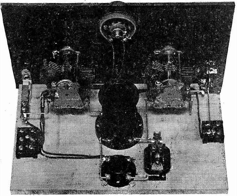
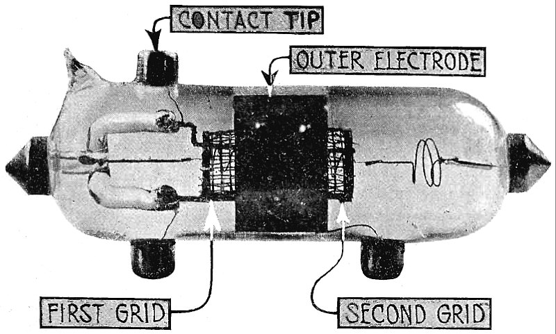
Internal Construction of Triplex Valve and Triplex Valve Mounted in Socket.
Articlke: Multi -Valve Systems. Performance of a Vacuum Tube Having Two or More Sets of Elements So That It Replaces Several Amplifier Tubes.
"All the tube elements necessary for a two-stage radio amplifier, or three-stage audio amplifier have been enclosed in a single tube not much larger than that ordinarily used in radio receivers. Such tubes have been developed by Dr. S. Lowe and the writer at Berlin where exceedingly satisfactory results have been secured. The original reason for doing this was to utilize ultra-short connections to reduce the stray capacities inherent in connecting several tubes. Not only has this been practically secured, but the cost of such a single tube is also less than that of the three which, it replaces..."
(Radio for June, 1927)
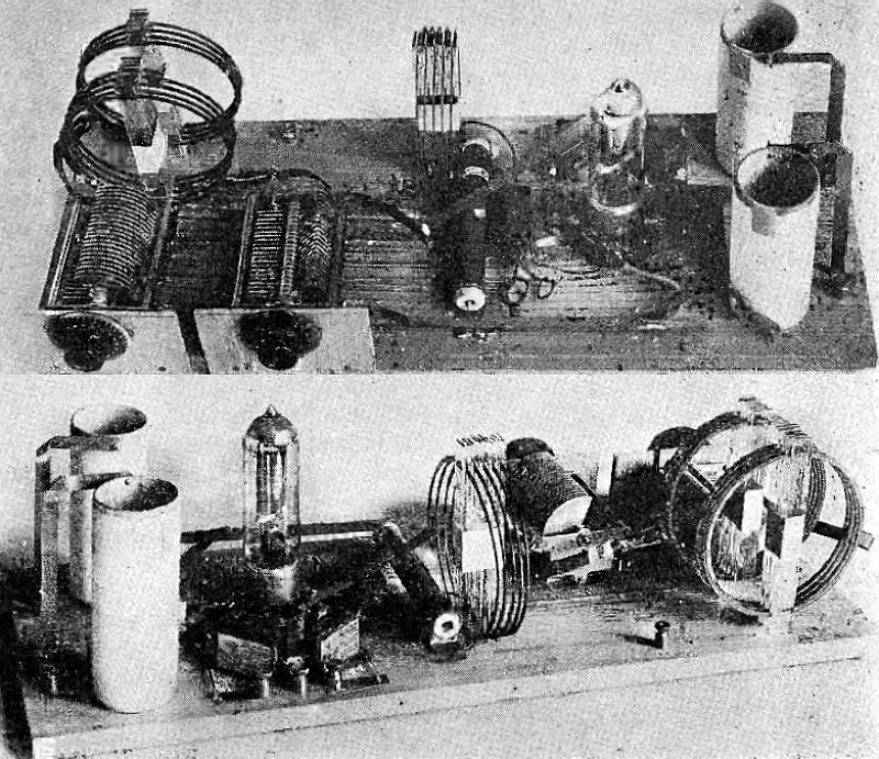
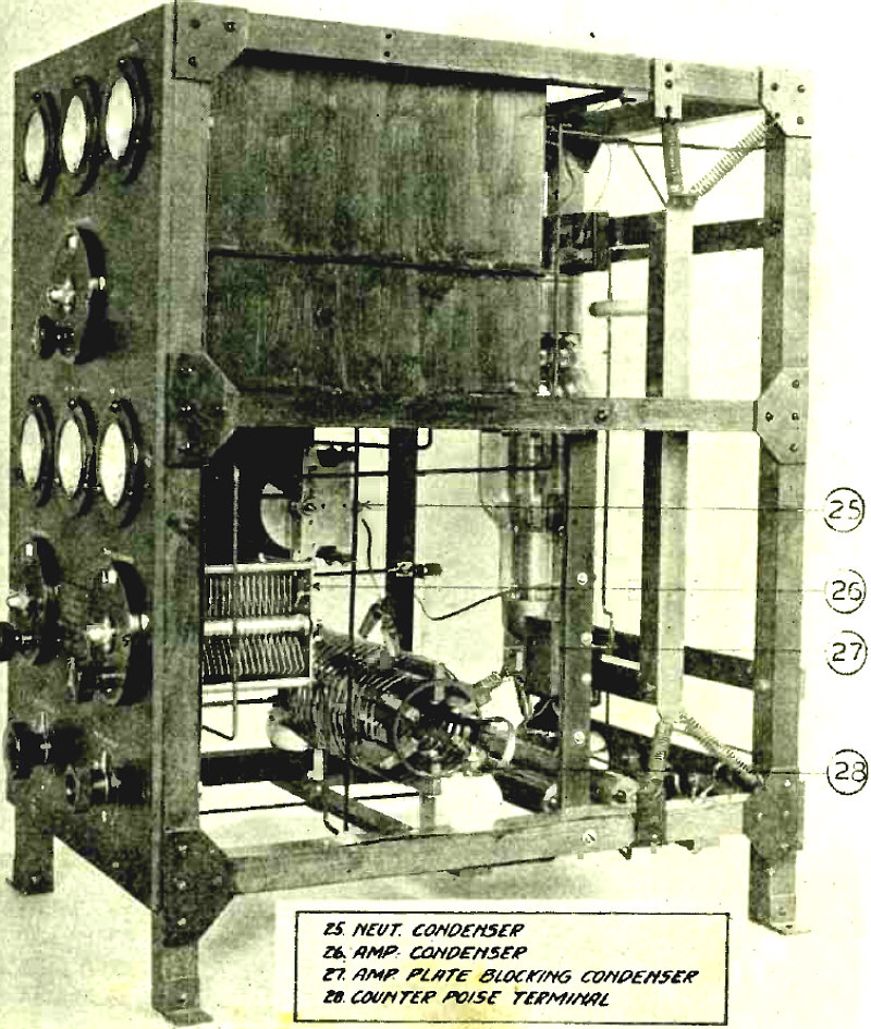
Arrangement on Base and Rear View of Transmitter.
Article: Laboratory Transmitter For Short Waves.
"This transmitter should appeal not only to traffic operators anxious to maintain their stations at topnotch efficiency but also to experimenters handling an occasional message. It is simple to construct and operate and is quickly adjustable to any one of the three short-wave bands in general use..."
(Radio for June, 1927)
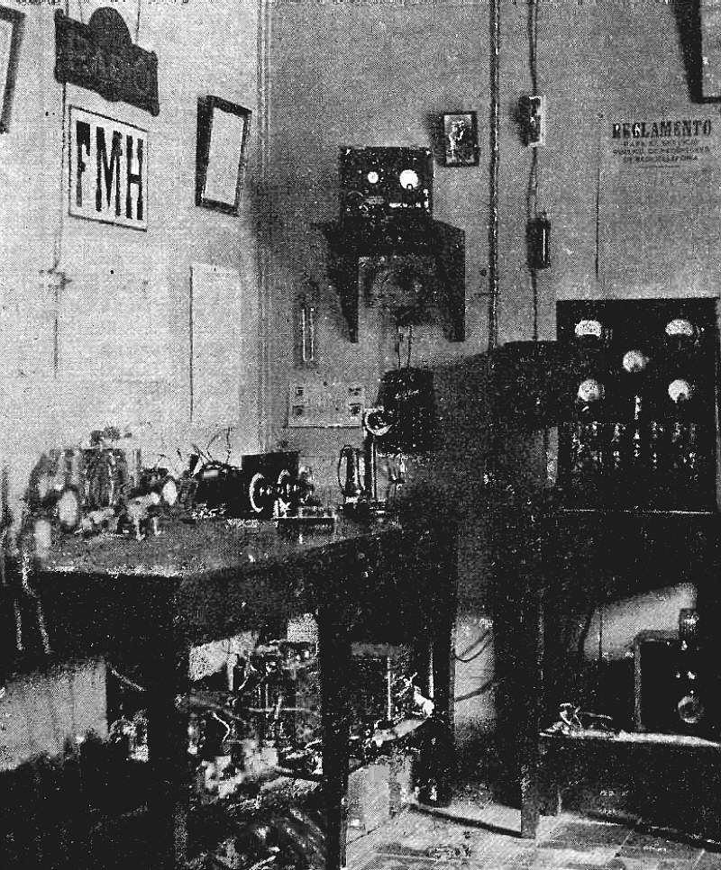
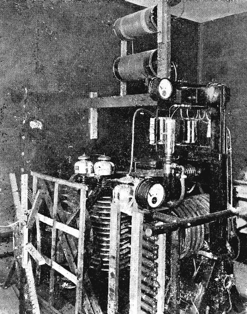
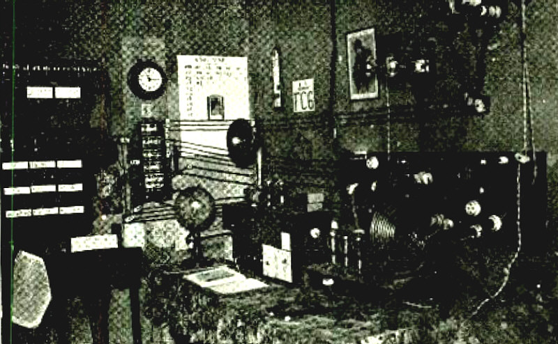
Radio Station NS-IFMH.
(Radio for June, 1927)
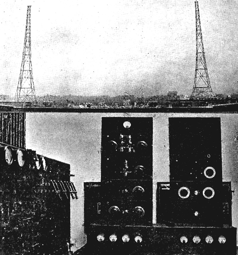
Type of Short -Wave Transmitter Used by R. C. A. Between Manila and San Francisco on 15 Meter (Daylight) and 30 Meter (Night) Service. This Equipment Uses Two Water-Cooled 20 K. W. Tubes and A Single 75 -ft. Vertical Antenna.
Article: Short Wave Communicatio in the Navy. An Authoritative Account of the Development of Short Wave Transmission by the Amateurs and of its Adoption by the U. S. Navy and Army.
"Few of us realize the important bearing of present day broadcasting and other radio activities upon the phenomenal distances being covered by short wave transmissions. The radio act of 1912 allocated wavelengths of not over 200 meters for amateur use and the wavelengths above 200 meters for commercial and military purposes. It was thought at the time that since amateurs would cover short distances the short wavelengths would suffice and that the longer wavelengths, which it was thought would cover longer distances, would be more suitable to commercial and military organizations. Little did the framers of the law know that wavelengths below 200 meters would receive the attention they are receiving today..."
(Radio for August, 1927)
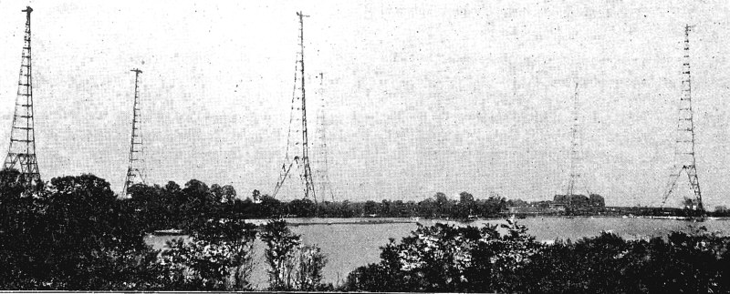
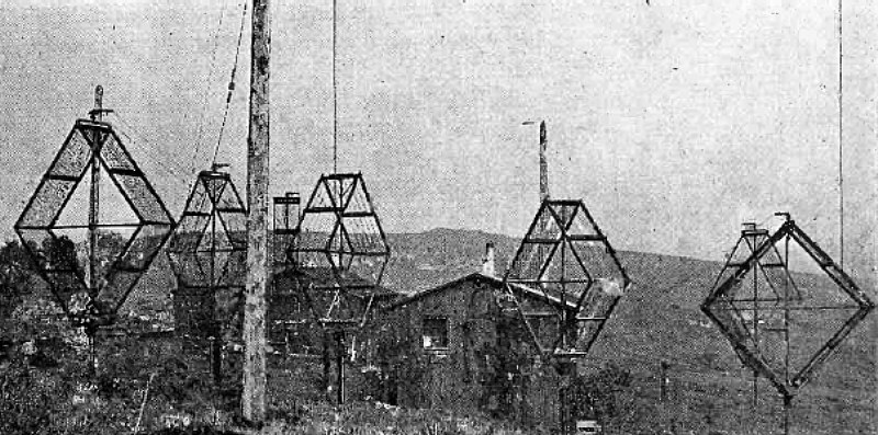
Elaborate Long-Wave Antenna System at Annapolis Which Can Be Replaced by 75 ft. Single Wire for Short-Wave Transmitter.
Article: Short Wave Communicatio in the Navy. An Authoritative Account of the Development of Short Wave Transmission by the Amateurs and of its Adoption by the U. S. Navy and Army.
(Radio for August, 1927)
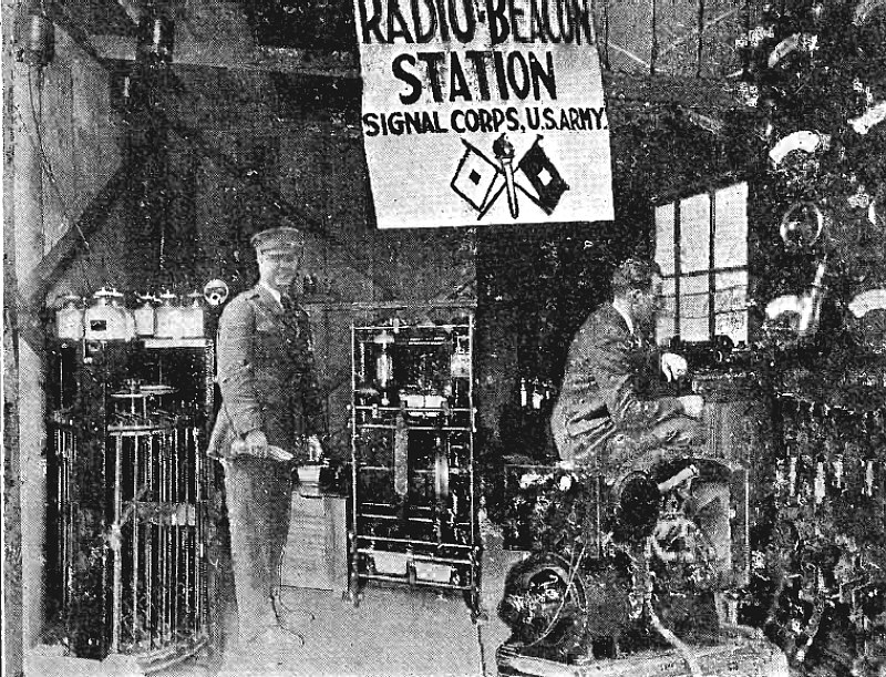
Beacon Equipment at San Francisco Presidio.
Article: Air Craft Radio Navigation. A Description of The U. S. Signal Corps Radio Beacon As First Employed in the Hawaiian Flight.
"Of the various aids to safety in flying one of the most promising is the radio beacon developed by Capt. Paul S. Edwards and his staff of Signal Corps engineers at the McCook Field, Dayton, Ohio. This system was given its first great practical application during the successful flight of Lieutenants Maitland and Hegenberger from San Francisco L Honolulu late in June..."
(Radio for August, 1927)
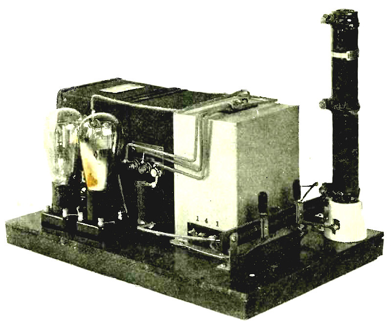
Two Stage Power Amplifier with Rectifier.
Article: A High Quality Power Amplifier. A 5-Watt Socket Power Device Which May Also Be Used To Supply Plate Voltage To A Receiving Set.
"The advantages of using a power tube having an undistorted audio output of several watts in the last stage are well known to those who have used the factory built power amplifiers employing the UX-210, CX-310 tube, or 205-D. Constructional details on power amplifiers using these tubes have appeared in past issues of RADIO, the most important having been by H. W. Armstrong in February, 1926 RADIO..."
(Radio for August, 1927)
Wiring Diagram Showing Apparatus Layout.
Article: A High Quality Power Amplifier. A 5-Watt Socket Power Device Which May Also Be Used To Supply Plate Voltage To A Receiving Set.
(Radio for August, 1927)
"I threw the switch and let him have it, and he came back."
Article: Sweetheart's Love Affair.
"Perhaps you read the first story about Sweetheart in the May, 1926 number of RADIO. You never happened to think, did you, that Sweetheart might be a real man? Well, he is. I was with him on the cruise down the coast of Africa, and when I decided it was time to get off a tramp steamer and get a job in the passenger service, which I did, who should turn up but Sweetheart! ..."
(Radio for August, 1927)
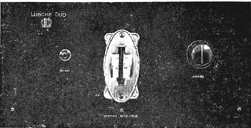
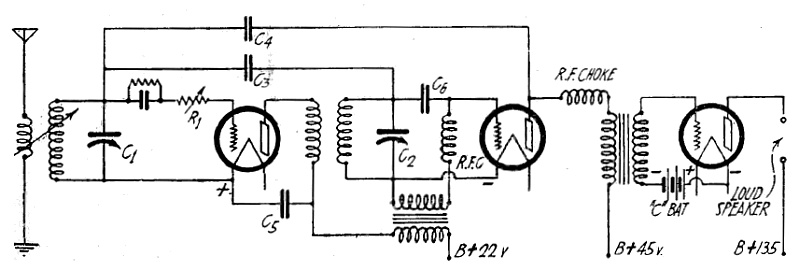
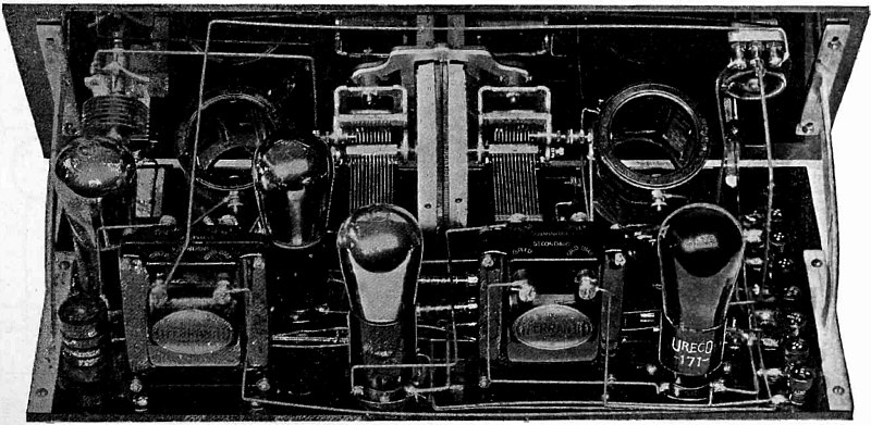
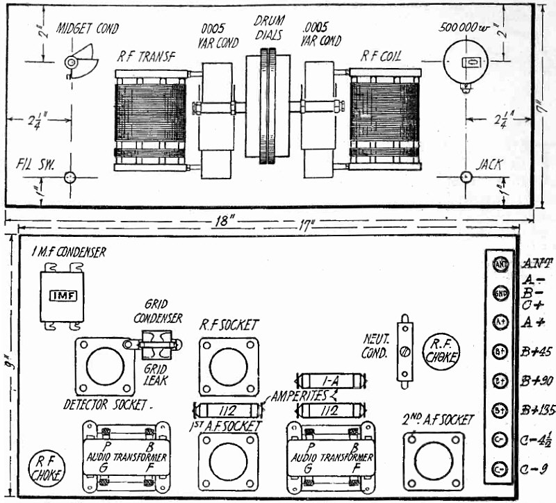
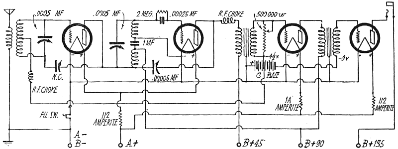
Panel View of Lubcke Duo.
Article: The Duo. A Two Tube Set Employing A Double-Grid Tube for R. F. and A. F. Amplification.
"With the advent of American quantity production of double-grid vacuum tubes the high per-tube efficiency of European receivers of more or less laboratory nature has become a reality for the broadcast listener. The Duo is a two tube receiver, constructed of readily obtainable standard parts, using a double-grid tube for dual amplification at radio and audio frequencies, and an alkali vapor tube as a regenerative detector. Through the use of efficient apparatus, matched and adjusted for maximum gain per stage, satisfactory loudspeaker operation is obtained; comparing favorably with three and four tube sets of conventional design. The receiver operates equally well with batteries or socket-power devices..."
(Radio for August, 1927)
Rear View of Duo.
Article: The Duo. A Two Tube Set Employing A Double-Grid Tube for R. F. and A. F. Amplification.
(Radio for August, 1927)
Advertisement
(Radio for August, 1927)
Advertisement
(Radio for September, 1927)
Advertisement
"Metrodyne" - All Electric Radio (7 Tubes Single Dial Set)
(Radio for September, 1927)
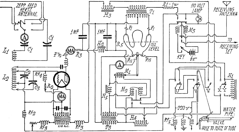
Transmitting Equipment at 3XN. Light Beam Driven From Hole at Right Passes Through Motor - Driven Screen in Center to Through Scanning Ray on Face of Speaker. Light Reflected Therefrom Causes Varying Electron Emission in Photoelectric Cells.
Article: Radio Television. A Simple Explanation and Description of The Bell Laboratories Successful Experiments.
(Radio for September, 1927)
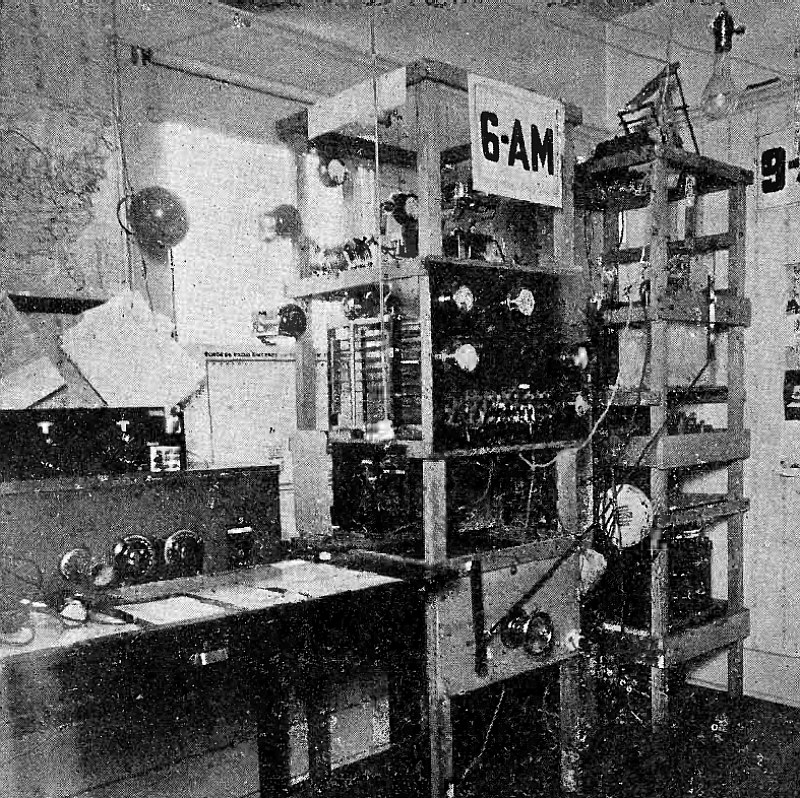
Circuit Diagram of Complete Transmitter at 6AM, with Mercury Arc and Water Cooled Tube.
(Radio for September, 1927)
Radio Station 8CAU.
(Radio for September, 1927)
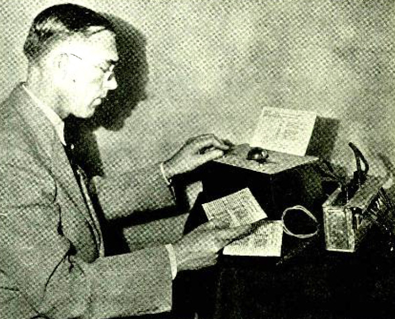
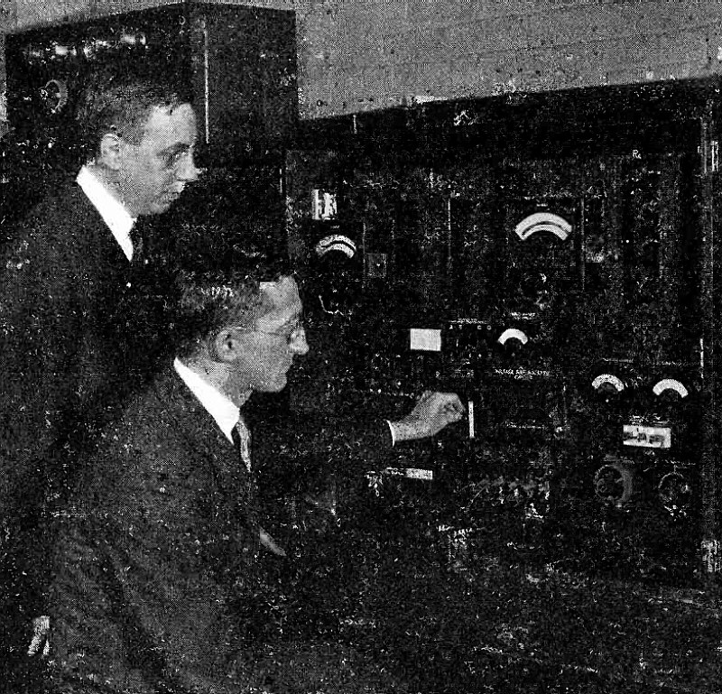
Continuity Tester in Use.
Article: How to Test Radiola Catacombs. Directions for Building and Operating A Continuity Tester of Inaccessible Radio Receiver Circuits.
(Radio for October, 1927)
Station sa-FC-6 Santa Fe, Argentina.
(Radio for October, 1927)
(Radio for October, 1927)
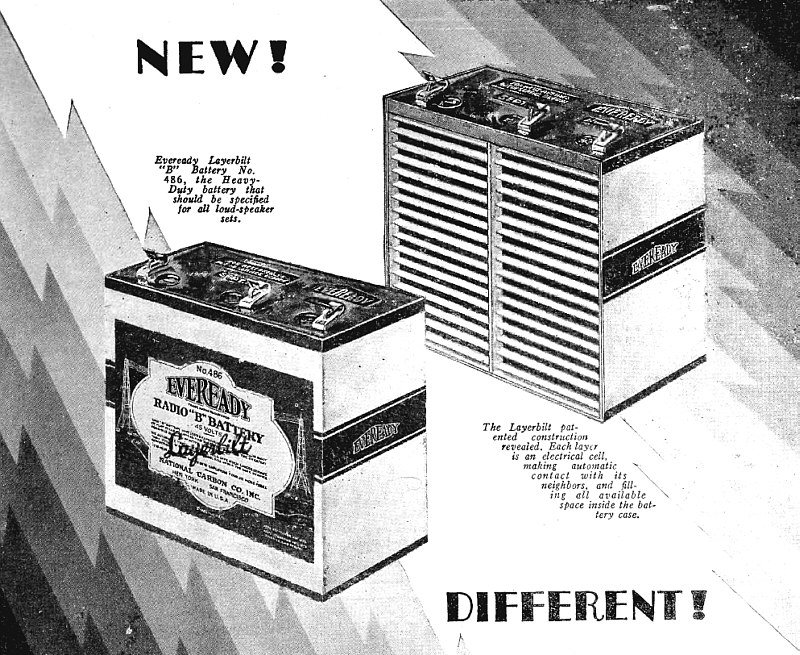
"Radio is better with Battery Power"
(Radio for October, 1927)
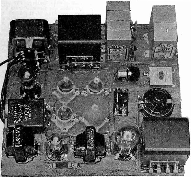
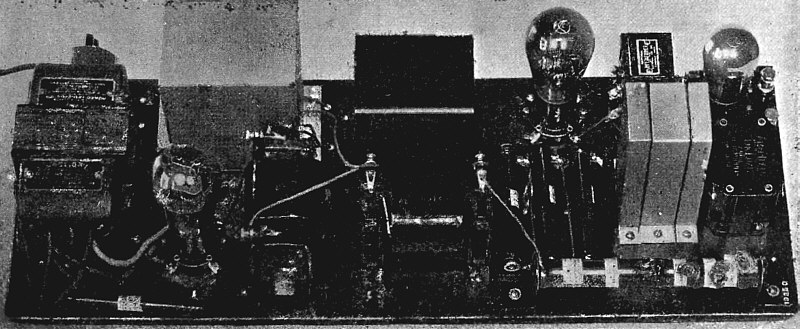
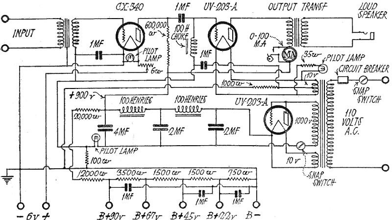
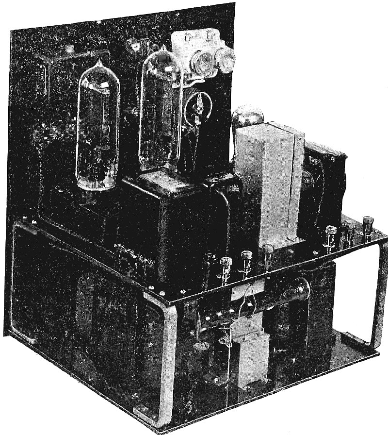
Panel View, With Amplifier Installed in Cabinet.
Article: A Heavy Duty Amplifier. A High Quality Audio Amplifier Giving Great Volume Over Wide Areas or Suitable for Use With A Phone Transmitter.
(Radio for November, 1927)
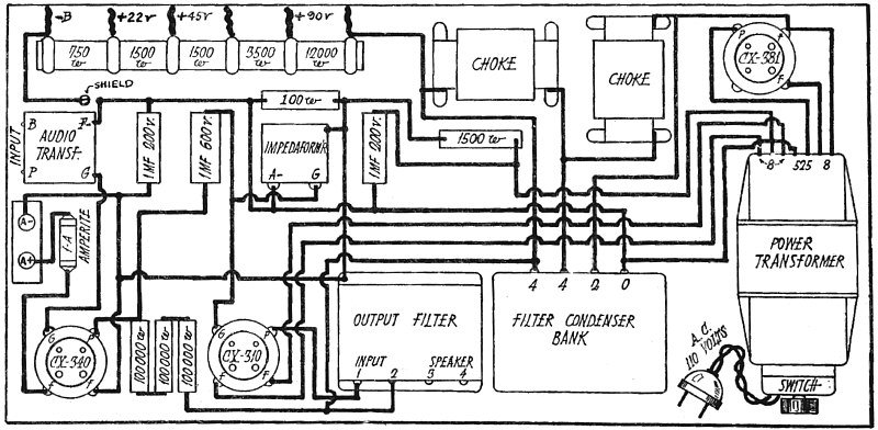
Wiring Diagram of Power Amplifier.
Article: A Heavy Duty Amplifier. A High Quality Audio Amplifier Giving Great Volume Over Wide Areas or Suitable for Use With A Phone Transmitter.
(Radio for November, 1927)
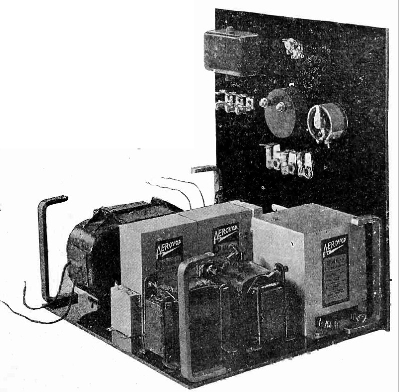
Rear View of Amplifier.
Article: A Heavy Duty Amplifier. A High Quality Audio Amplifier Giving Great Volume Over Wide Areas or Suitable for Use With A Phone Transmitter.
(Radio for November, 1927)
Bottom Shelf Assembly, Before Start of Wiring.
Article: A Heavy Duty Amplifier. A High Quality Audio Amplifier Giving Great Volume Over Wide Areas or Suitable for Use With A Phone Transmitter.
(Radio for November, 1927)
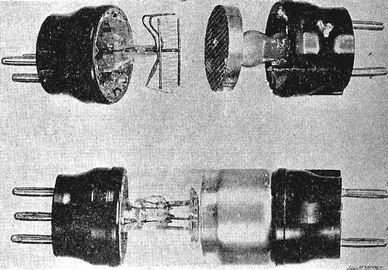
Marconi Shielded Valve.
Article: A New Shielded Grid Tube.
(Radio for November, 1927)
(Radio for November, 1927)
(Radio for December, 1927)
1/4 K.W. High Frequency Transmitter Used in Naval Radio Service.
Article: Navy Radio High Frequency Communications.
(Radio for December, 1927)
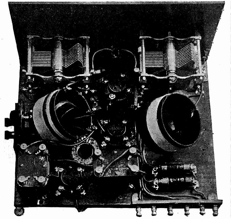
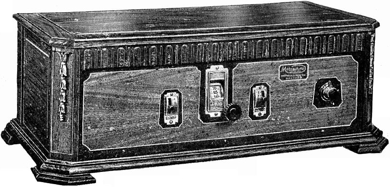
Power Supply Unit.
Article: Socket Power Operation of The Tyrman Ten.
(Radio for December, 1927)
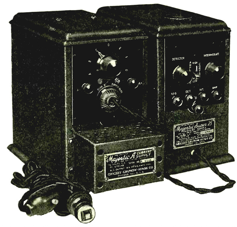
Electrify Your Radio Set With Majestic "A" and "B" Electric Power Units.
(Radio for December, 1927)
")
")
")
")
")