A.W., "20W÷35W tube audio amplifier"
Radioamator i Krótkofalowiec 1974/09
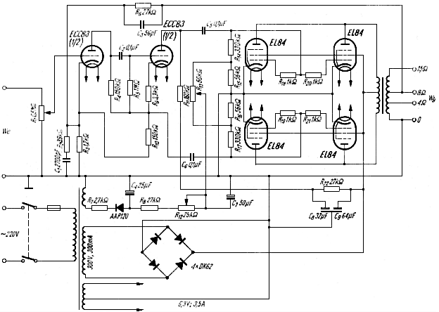
The scheme of 35W tube amplifier is shown in the picture. A characteristic feature of the amplifier is the use of four popular EL84 lamps in the final stage. It is unnecessary to describe the performance of the amplifier; it can be successfully built by more advanced radio amateurs, for whom the scheme itself explains almost everything.

Schematic diagram of a 35W acoustic tube amplifier
Let us, however, pay attention to what seems less obvious or does not follow the pattern.
The use of four EL84 tubes gives the following benefits:
- anode voltage is relatively low (300V), which facilitates the selection of the network transformer and electrolytic capacitors of the filter,
- in AB1 class, the control voltage is low and you can control the entire final stage from a conventional phase inverting stage,
- the best working resistance has a small value (4000 ohms from the anode to the anode), which facilitates the construction of the output transformer and the use of deep negative feedback (up to 25dB). It should be reminded that the AB1 class is particularly beneficial, because it does not cause problems with distortions at small and medium amplitude values, which are sometimes unpleasant in the case of not sufficiently refined Class B amplifiers.
The negative voltage of the end stage tubes is obtained from a separate rectifying system; it allows setting the initial working point of the tubes (potentiometer R12) and symmetrical setting of the operation of the push-pull circuit (potentiometer adjustable R13). The power supply can be of any type. With an anode voltage of 250V, it is possible to obtain an output power of up to 20W at a maximum current consumption of 180mA. However, it is appropriate to use a good 300V, 250mA power supply with low internal resistance so that the voltage does not decrease with current changes from about 160mA to 230mA. The filter can of course be expanded using a choke and an additional electrolytic capacitor. Instead of semiconductor diodes, selenium rectifier systems can be used. The negative voltage is obtained either from a separate winding of a 25V mains transformer (5mA load) or by using an additional transformer (eg a scrolled "bell" transformer).
The quality of the amplifier's operation depends mainly on the output transformer. It should be perfectly made (selectively, symmetrically wound with a sufficiently large core) transformer with significant inductance of the primary winding and low value of dissipation inductance.
The indicative transformer technical data in case of the need to meet the Hi-Fi requirements are as follows:
- cross section of the core: 20÷25 cm2,
- inductance of the primary winding: 70÷90H,
- resistance of the primary winding: no more than 2x100 ohms,
- inductance of dispersion (all primary to secondary): on the order of 10mH,
- primary impedance (from anode to anode): 3600 ÷ 4000 ohms,
- outoput transformet secondary to primary ratio adopted to the anticipated load.
Resistor R6 resistance in the negative feedback loop is given for a secondary winding designed to connect a 8 ohm load; when making a transformer designed exclusively for a 4 ohm load, the value of the R6 resistor should be reduced by 30%.
For smaller requirements, a "savings" transformer can be used, limiting the frequency response band and reducing the depth of the negative feedback applied.
Technical data of a well-made amplifier in the Hi-Fi version are as follows:
- output power: 20W at h <= 0.4% (40Hz and 1000Hz),
- output power: 35W at h <= 3.0% (1000Hz), power for music (instantaneous) can reach 40W,
- frequency response band: 20 ÷ 50000Hz,
- input sensitivity: around 1.0V (depends on the depth of the negative feedback).
Optimum working conditions of the tubes: 300V anode voltage, 36mA anode current (for one tube), maximum anode current at the most permanently given power of 46mA, the largest secondary grid current 11mA.
If you do not use full power, you can reduce the anode current to 30 ÷ 25mA (one tube) somewhat.
The schematic diagram and data of the amplifier are taken from the book: E. Rodenhuis - Hi-Fi Amplifier Circuits. Philips Technical Library, Eindhoven. The rectifier system has been changed.
A.W.


