DESIGN OF OUTPUT TRANSFORMERS
Radio amateur and amateur radio operator of Poland, Year 24, December 1974, No. 12.
Low-frequency tube amplifiers, especially with higher power, are still built by radio amateurs. The output transformer is the most difficult element to design and manufacture. This is evidenced by inquiries and requests for help in the calculations sent to the editorial office. The basic principles of designing transformers intended to be made in amateur conditions presented here briefly should satisfy the wishes of interested readers.
The principles of designing low-frequency transformers in amateur conditions are slightly different from those used in industry. First of all, it is determined approximately what core is needed for the designed amplifier. Then a more or less suitable core is searched for, and after it is acquired, further winding calculations are made. After establishing approximate data as to the necessary winding wires, wires with diameters similar to the selected ones are purchased and only then the number of turns of individual windings is finally determined.
The basic relationships linking the phenomena in a transformer result from the following formula:
Etr = 6,28⋅f⋅n⋅Q⋅B⋅10-4 (1)
where:
- Etr - the amplitude of the reverse-electromotive force induced in the primary winding, approximately equal to the amplitude of the supplied voltage [V],
- f - frequency [Hz],
- Q - core cross-section [cm2],
- n - number of turns of the winding,
- B - the highest induction value in the core [T].
The value of the reverse electromotive force is related to the alternating voltage of the final amplifier stage and results from the power and operating resistance. The highest and the lowest frequency of the passband results from the assumptions. The highest allowable induction value in the core should not exceed 0.6T. For Hi-Fi amplifier transformers, it is recommended to take 0.4T. Two unknowns remained in the formula given: the core cross-section (Q) and the number of turns (n). We determine the core cross-section approximately from the formula:
where:
- Pwy - the output power of the amplifier.
As far as possible, we aim to build a transformer with a large core cross-section, which will allow to reduce the number of turns in the windings. This is important both due to the undesirable leakage inductance of the transformer and the degree of difficulty of its manufacture. In transformers composed of sheets with holes for fastening bolts, it is necessary to check that the core cross-section near the bolts is not smaller than that of the main column.
The simplified transformer substitute circuits are shown in Fig. 1. At the lowest frequency, the influence of the inductance of the transformer primary winding, which is connected in parallel to the appropriate amplifier load, should be taken into account. In most cases, it is the necessity to obtain a sufficiently large value of this inductance that determines the number of turns of the primary winding. At medium frequencies (1000Hz is assumed), only the winding resistances play an important role. At high frequencies, the influence of the leakage inductance is noticeable, the value of which depends on the number of turns, the transformer winding scheme and its quality. This inductance, in combination with the inter-winding capacitances, creates a low-pass filter limiting the transformer bandwidth..
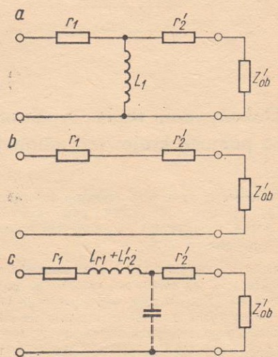
Fig. 1. Simplified equivalent transformer diagrams.
a - equivalent circuit for the lowest frequencies,
b - equivalent circuit for medium frequencies,
c - equivalent circuit for great frequencies (treble and ultrasound).
r1 - primary winding resistance,
r'2 - secondary winding resistance transferred to the primary side,
Zob - load impedance,
Z'ob - load impedance transferred to the primary side,
L1 - primary winding inductance,
Lr1, L'r2 - winding leakage inductance.
In well-made transformers the cut-off frequency is around 100kHz. In any case, it should have a value several times higher than the adopted upper frequency of the amplifier's passband.
Using the formula (1) and substituting the appropriate values in it up to the core cross-section, we determine the number of turns n.
Then, using the formula (3) and assuming the minimum required inductance of the primary winding L1, we calculate the number of turns n1. We compare the value of n and n1. We take the greater value for further calculations.
The formula for calculating the approximate number of turns with the assumed inductance is as follows:
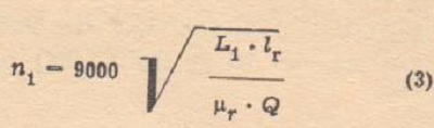
where:
- n1 - number of turns of the primary winding,
- L1 - primary winding inductance [H],
- lr - the average length of the magnetic flux path in the core [cm],
- μr -magnetic permeability of the core; for transformer steel and output transformers it is assumed μr=500,
- Q - core cross-section [cm2].
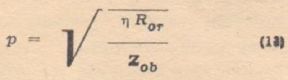
The inductance of the primary winding should be such that the winding reactance at the lowest passband frequency is greater than the working resistance of the final amplifier stage, which can be expressed by the formula:
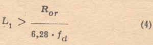
where:
- fd - lowest frequency of passband [Hz],
- Ror - the working resistance of the final stage (in the case of push-pull systems from anode to anode or from collector to collector).
The energy efficiency η of the output transformer should be high and amount to η = 0.80 ÷ 0.90. It depends primarily on the winding resistance r1 and r2. Appropriate practical mathematical formulas.
For Class A amplifiers:
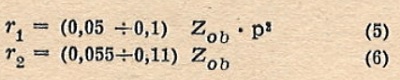
For Class B amplifiers:
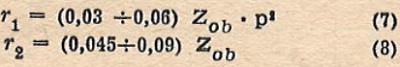
where:
- Zob - speaker unit impedance [Ω].
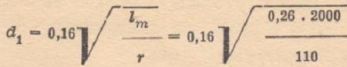
Winding wire diameters (without insulation) are calculated from the formula:
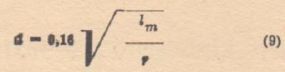
where:
- d - wire diameter [mm],
- lm - the length of the wire in the winding [m],
- r -winding resistance [Ω].
The transformer turn ratio depends on the load impedance and transformer efficiency. The corresponding mathematical formula is:
We treat the calculated number of turns, winding resistances and wire diameters as preliminary data, subject to correction after purchasing the wires and designing the body on which we will wind the windings. As a rule, windings are divided into sections. The primary winding can have 4, 6 or 8 sections. The primary winding sections should have an even number of layers - only then the ends of the sections will be on the outer side of the body and it will be possible to lead them outside. Most often this applies to the secondary winding section, although in this case it is easier to make internal connections if necessary.
In the case of class A and AB1 amplifiers, we strive to obtain a low value of the leakage inductance between the primary and secondary windings. It is allowed to wind the primary winding as shown, for example, in Fig. 2a. For class B and AB2 amplifiers, care must be taken to ensure good coupling between each primary half and the entire secondary winding, as the primary winding halves operate unbalanced. An example of the arrangement of sections is shown in Fig. 2b.
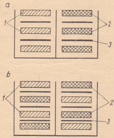
Fig. 2. Schemes of the arrangement of the transformer winding sections.
1 - sections of one half of the push-pull winding,
2 - sections of the second half of the push-pull winding,
3 - secondary winding sections.
After the transformer body (carcass) has been manufactured, a test is carried out to determine the number of turns in one layer. Based on this, it is possible to determine the number of turns of the section and the winding scheme of the entire transformer by correcting the total number of turns of the primary and secondary windings, respectively.
Example
(This example includes the calculation of the transformer for the tube amplifier described in the issue 9/1974 of our monthly magazine. In the book from which the amplifier diagram is taken, only the electrical data of the recommended transformer without design data is given. The rules for calculating transformers are described in more detail in the books: G. Cykin - Electric signal amplifiers, WKŁ Warszawa, and A. Witord - Amateur electroacoustic amplifiers, WKŁ Warszawa)
A transformer for a 35W tube amplifier should be designed. The working resistance of the PP stage (from anode to anode) is 4000Ω according to the catalog. Amplifier passband 40Hz ÷ 15000Hz. 4Ω load impedance. We assume the permissible induction is B-0.6T.
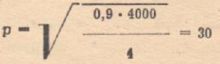
1) Core cross section desired:
![]()
2) We purchased a core with the dimensions of a 50x50 center column and a 25x75 window. We assume the cross-section of the core 23cm2.
3) We pre-calculate:
- from the condition for induction in the core (formula 1):
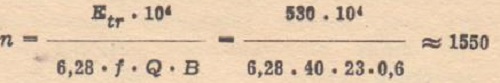
In the above formula, knowing the amplifier power and working resistance, the Etr value is calculated as follows:
![]()
- from the condition to inductance assuming L1 = 20H:
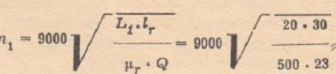
we get approximately 2000 turns.
- the ratio of turns between turns:
- primary winding resistance:
![]()
- secondary winding resistance:
![]()
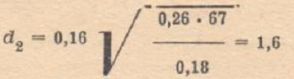
- winding wire diameter - assuming an average coil length of 0.26 m and 2000 windings:
which gives the value d1 = 0.35.
4) We managed to purchase ø0.40 and ø0.8 wire in enamel insulation.
The body glued from a pressboard has the dimensions shown in Fig. 3. Without a winder for winding transformers, but only a makeshift device of our own design - we decide on a fairly simple winding scheme: primary winding - 4 sections, and secondary winding - three sections connected in parallel (Fig. 4).
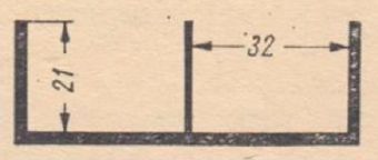
Fig. 3. Body dimensions (calculation example).
The winding test showed that there is an average of 60 turns in one layer of the primary winding section. We take 8 layers per section for a total of 480 turns. The four primary winding sections will have a total of 1,920 turns. The secondary winding will consist of 3 sections wound along the entire width of the body (in one layer), each with 64 turns. These sections will be connected in parallel.
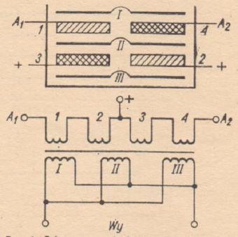
Fig. 4. Scheme of the winding of the output transformer (calculation example).
We check again whether the calculations are correct and whether the winding will fit in the body. The primary winding (16 layers) is about 8mm, the secondary winding (3 layers) is less than 4mm. As the free space in the body is 21mm, there is at least 9mm for insulating spacers, which is more than enough provided that it is tightly wound and the spacers made of capacitor paper or special transformer paper are used. Better insulation of oilcloth or a thin pressboard impregnated with bakelite varnish, shellac or other good insulating medium should be used between the primary and secondary windings.
For complete symmetry, windings 1 and 2 are wound in one direction, and windings 3 and 4 in the opposite direction. Only then will the anodes (collectors) fall out at the end of the uppermost section.
A few additional comments. In the case of purchasing a ø0.35mm wire, the body - with a winding of 2000 turns and the same winding pattern - would not be properly completed. A system of 4 primary sections (450 turns in 6 layers) can then be used with a total number of turns 1800, leaving the previous secondary winding system. Alternatively, the alternative of increasing the primary winding to 2400 turns may be considered by changing the layout (and wire) of the secondary winding. Increasing the number of turns is advantageous because the inductance of the primary winding (L1) will increase with slightly deterioration of other parameters.
A.W.