Radioamator i Krótkofalowiec polski, Rok 14, Maj 1964 rok, Numer 5.
(Radio amateur and amateur radio operator, Year 14, May 1964, Number 5.)
mgr Zdzisław Krzystek.
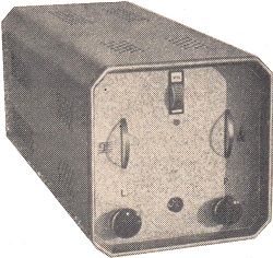
The apparatus consists of a "Ziphon" turntable, a 2x4W wideband amplifier and two loudspeakers in closed housings with an opening. It provides sufficient volume for the reproduction of music in the living room.
AMPLIFIER
The schematic diagram of the amplifier is shown in Figure 1.
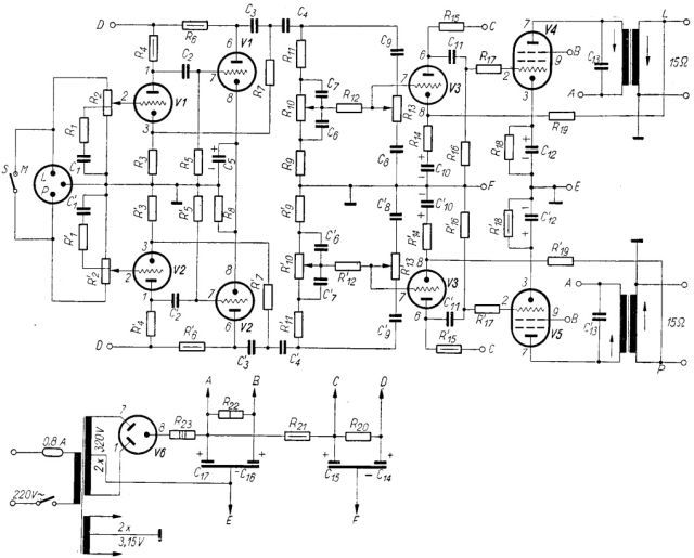
Figure 1. Schematic diagram of the amplifier.
There is a "Mono-Stereo" switch at the amplifier's input, which should be closed when reproducing monophonic recordings. This slightly reduces the noise from the turntable, as the transducer is then insensitive to the penetrating vibrations of the needle (note: this switch is not present in the photos).

R2 and R'2 log potentiometers are separate left and right gain controls. Their resistance - as required by the KSS0160 type phono cartridge used - is 1MΩ. C1R1 shunts are not necessary; they are the physiological correctors of hearing, which counteract the subjective disappearance of bass tones while turning down the playback of a vinyl record.
The V1 (V2) electron tube, double triode, operates in a two-stage preamplifier system with fifteen times negative feedback. By appropriately selecting the capacitance of the capacitors C2, C3, C4, a sharp cut-off of vibrations with a frequency below the playback range (21dB / octave below 35Hz) is obtained. Such vibrations arise in the drive system of the turntable. This cut-off also reduces the possibility of acoustic feedback between the speakers and the turntable. The feedback provides a small (dynamic) input capacitance (necessary due to the high resistance of the potentiometers), a low output resistance (needed for the correct operation of the tone equalizers) and a negligibly low coefficient of the preamplifier hoarseness (0.02% at full control). The voltage gain is 100 times.
Mechanical coupled potentiometers R10 and R'10 are used to adjust the intensity of tones below 800Hz, and the coupled potentiometers R13 and R'13 - to adjust the intensity of tones above 2000Hz. These potentiometers are linear, thanks to which it is easy to select items with sufficient concurrency, and moreover, in the construction shown in Figure 2, they rotate in the opposite direction.
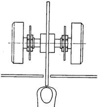
Figure 2. Mechanical coupling of the potentiometers regulating the timbre.
The third stage (voltage amplifier) and the output transformer have a 10-fold, frequency-independent negative feedback. The capacitor C10 (C'10) corrects the amplitude and the phase changed by the transverse inductance of the output transformer. Such a correction prevents the formation of sub-acoustic vibrations with strong feedback and additionally reduces the sensitivity of the amplifier below the radiation range of the loudspeaker system. The hoarseness coefficient at 3W power does not exceed 1%, the damping coefficient (the ratio of working resistance to output resistance) exceeds 10.
Common ground points are clearly marked in the amplifier schematic. The matter of the choice of earthing is usually underestimated, and it is of fundamental importance in the generation of interfering voltages (hum).
When connecting the source and receiver with high impedances in the range of higher acoustic frequencies, the use of shielded cables should be avoided so as not to impair the reproduction of high tones. This is usually possible with proper spatial planning. In the described amplifier, the only shielded wire is to lead the mains supply circuit to the switch located on the front panel.
OUTPUT TRANSFORMERS
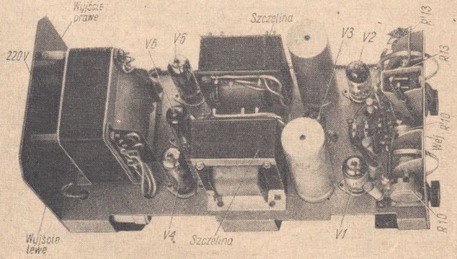
Requirements: resistance transformation from 7kΩ to 15Ω, constant current component 40mA, transverse inductance 22H, longitudinal inductance maximum 75mH (i.e. transmission range 50Hz - 15kHz). You can use the Tonsil TW 6-312 transformer with a properly set gap or wound on the core (EI 84/28 core cross-section area 7.8cm2 gross) as follows: primary winding in two sections connected in series with 1460 turns 0.17mm, intertwined with the secondary winding consisting of three serially connected sections, 48 turns 0.65mm each. The thickness of the paper in the air gap should be selected so that a current of 30-33mA flows through the transformer at 220V AC (50Hz) supplied to the primary winding. The output transformers should be positioned on the base of the amplifier so that the air gaps are on the side away from the mains transformer - as shown in the photo.
POWER SUPPLY TRANSFORMER
The AC adapter is to deliver: 92mA DC at 320V and 2.5A AC at 6.3V. Assuming the magnetic induction amplitude in the core equal to 10kGs, the current density in the windings 2.5A / mm2 and the core cross-section area of 12cm2 gross, the following should be wound: mains section (220V) - 888 turns, 0.45mm; rectifier section 1330 + 1330 turns, 0.23mm; glow section 26 turns, 1.3mm with a tapping in the middle.
When using a different core, the number of turns should be changed inversely to the cross-sectional areas of the cores. The filament voltage is a critical quantity. If the number of turns is not a whole number, it should be rounded up and the remaining windings counted in relation to the filament windings.
PRACTICAL NOTES
Before starting the assembly, it is advisable to check all elements by means of measurements. Before first connecting to the mains, you should: insert the appropriate fuse, short-circuit the outputs, set the regulators to minimum, check with an ohmmeter the insulation between the cathode of the rectifying tube and the ground and the conductivity between this cathode and the anodes of the output tubes. After switching on, we check that the output tubes are not overloaded; the cathode voltages are to be 6.6V. The supply voltage (320V) can be corrected with the R23 resistor, and the output tube currents (40mA) with the R22 resistor. The measurement should be performed after the tubes have been heated up for a few minutes and at the nominal voltage of the supply network.
SPEAKER SETS
Each set includes two Tonsil GD 31-21 / 5 mid-woofers with 15Ω impedance at 1000Hz and 40Hz resonance frequency, and the GDW 12.5 / 1.5 tweeter with 8Ω impedance at 3000Hz. The loudspeaker connection diagram is shown in Figure 3..
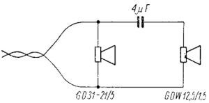
Figure 3. Connecting the speakers in one set.
Mark the polarity of the speakers as follows. We put a flat battery so that the diaphragm tilts forward. The end of the loudspeaker connected to the positive battery terminal is usually marked with a red dot. When the M-S switch is closed, the diaphragms have to vibrate in-phase.
Figure 4 shows the simplest closed housing design with an opening. Two symmetrical mirrors should be made and placed in two corners of the room.
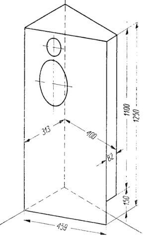
Figure 4. Left loudspeaker housing. The use of a corner of the room enables an economical construction consisting of only three walls of the housing. The capacity of the box is 100dcm3. Internal dimensions are given in mm.
The dimensions should be selected so that the speaker axes intersect at an angle of 600. Surrounding the intersection of these axes is the best place to listen to stereo recordings.
More detailed instructions on how to make the casing can be found in A. Witort's book "Elektroacustyka for everyone". In a long acoustic chain, the first link of which is the concert hall and the last link - the listening room, the weakest link contributing the most distortions is the loudspeaker system. Therefore, this issue should be given the most attention.
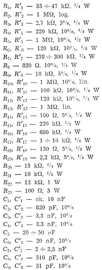
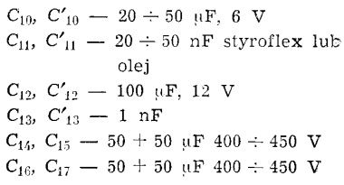
ELECTRICAL VALUES OF RESISTORS AND CAPACITORS
ERRATA (Radio amateur and amateur radio 1964/07)
o the article entitled "High-quality stereo gramophone apparatus" (No. 5/1964) introduces the author (mgr Zdzisław Krzystek) the following additions and corrections:
- Tubes V1, V2, V3 - 3 x ECC83
Tubes V4, V5 - 2 x EL84
Tube V6 - EZ81. - The half of the V3 duotriode operating in the right channel of the amplifier should have electrode numbering 1, 2, 3 and not 6, 7, 8.
- The diameter of the power supply wire of the network winding is to be 0.42mm, not 0.45mm.
A 0.5A mains fuse is sufficient. - The capacity of the C5, C10, C'10 capacitors is to be 50μF ÷ 100μF, not 20μF ÷ 50μF.
- Data of the mains transformer on the core from the "Symphony" receiver:
- core M100 / 35, gross cross-sectional area 9.8cm2.
- mains winding (220V) - 1082 turns, ø0.42mm.
- anode winding 1630 + 1630 turns ø0.23mm.
- filament winding 34 turns, ø1.2mm.
- Power consumed by the amplifier 70W.
This interesting article from the past was painstakingly typed by Grzegorz Makarewicz "gsmok"