Andrzej Depczyk, "10W Hi-Fi amplifier"
Radioamator 1957/12
In recent times, significant progress has been made in low frequency technology. The increasingly demanding requirements for this branch of technology by users led to the creation of high-quality recordings (frequency range 30 ÷ 16000Hz - with distortions <2%) and to popularize UKF-FM radio reception. Having good music sources, it is necessary to use amplifying devices that would not degrade the quality of production played by a high quality adapter or a UKF-FM receiver.
This amplifier, referred to as Hi-Fi, should provide:
- sufficient volume of the broadcast in the room,
- linear frequency characteristics within the limits of audibility,
- small non-linear distortions so small that a human-trained ear could not detect them.
The first condition can be met if the power amplifier will be able to deliver about 10W to the loudspeaker; This does not mean that the amplifier should work all the time at full power, because nobody would stand it, but the amplifier's ability to give 10W power at the top of the program allows for high dynamics and prevents overdriving.
The second condition will be fulfilled by the amplifier whose frequency characteristics will be linear in the range of 20 ÷ 30Hz to 15000 ÷ 20,000Hz.
The third condition is generally the most difficult to meet; Nonlinear distortions should be less than 2% and not only harmonic distortions, but comprehensive (intermodulation) distortions.
There are a number of high-quality amplifier circuits, but these are generally very expensive devices. J.M. Miller has developed a simple and relatively inexpensive system of the amplifier, which after some modification meets all the above requirements.
In its original version, the amplifier was equipped with a transformer with a core cross section of 3.6 cm2, wound plainly, without dividing the windings. This amplifier had frequency characteristics of 20 ÷ 50000Hz +/- 4dB, nonlinear distortion (harmonics) of 0.35% at 400Hz and 8W. The amplifier described in this article differs from its prototype application:
- transformer with divided windings,
- additional phase correction in the high frequency range,
- corrector of response characteristics.
Circuit description
The amplifier, the diagram of which is shown in Figure 1, consists of a preamplifier stage with a equalizer that allows changing the frequency characteristics at the end of the range within +/- 15dB, then with two stages of a voltage amplifier, phase inverter and final stage in a push-pull circuit.
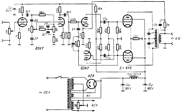
Fig.1. Diagram of a 10W Hi-Fi amplifier
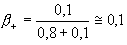
It has two basic feedback circuits. The first circuit is a positive feedback loop and includes one stage preamplifier; the voltage of this coupling, taken from the grid of one of the end lamps and through the resistor of 0.8M and the capacitor 6pF, is applied to the grid of the last stage of the preamplifier. A voltage divider is created from resistors 0.8M and 0.1M (previous tube - triode with very low internal resistance), so that the positive feedback coefficient is:
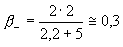
The second feedback - negative - includes the output transformer and through the 5K resistor is applied to the cathode of the last stage of the preamplifier. A 200pF capacitor parallel to the 5K resistor introduces a phase correction for high frequencies. The negative feedback factor is:
With both feedback loops, the resultant gain change is around -9dB, so even though a significant negative feedback is applied, the drop in sensitivity of the amplifier is insignificant.
Co-operation of both couplings, so-called balanced feedback, reduces nonlinear distortion and contributes to reducing the internal resistance of the amplifier to almost zero, which significantly improves the conditions of cooperation with the loudspeaker, especially when reproducing impulse waveforms.
The design of the amplifier
The amplifier was built on the chassis from the "AGA" receiver, so it takes up quite a lot of space and the distances between the individual elements are significant. Such a solution with careful assembly allows to reduce the hum of the network, which is -64dB and eliminate harmful feedback.
The resistors and capacitors used to build the amplifier should have a tolerance of +/- 10%.
The first 6SN7 lamp should be shielded with a metal cup (high sensitivity to the effect of the hum of the network).
The output transformer is the structural element of the amplifier, which poses the most difficulties. In the model amplifier, the transformer was wound on a core with a cross section of approximately 7 cm2 and the dimensions given in Fig. 2.
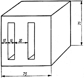
Fig.2. The core used to make the output transformer
The output is adapted to a loudspeaker or speaker set with a resistance of 4 ÷ 6 ohms. Since the most favorable load resistance of 6V6 lamps in the push-pull system in class AB1 is 8000 ohms, the transformer ratio should be about 40.
The winding system is shown in Fig. 3. Arrows indicate the direction of winding of individual coils.
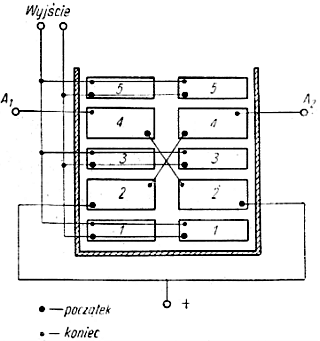
Fig. 3. The location of the transformer's output coils
Coils marked with numbers 2 and 4 should be wound with enamelled Cu wire, 0.12, 950 turns, keeping the direction of the windings; and coils 1, 3, 5 - enamelled Cu wire 0.3 by 95 turns, inserting a waxed paper spacer between the individual coils. The coils must be connected in the manner shown in Fig.3. The core consists of no gap. Details of the structure can be solved arbitrarily while maintaining the generally applicable rules.
Results
The amplifier was loaded with a 5 ohm resistor. Frequency characteristics are linear within 20 ÷ 20000Hz, with deviations not exceeding - 0.3dB. Nonlinear distortion (harmonics) at 10W and frequency 1000Hz is 0.21%, at 13W power - 0.82% and finally at 15W - 4%. Distortion measured at 40Hz and 10W power was 0.6%.
The voltage jump after disconnecting the load at 1000Hz is 0.1 dB, which indicates very low internal resistance of the amplifier.
The characteristic of the harmonic content factor is shown in Fig. 4, and frequency characteristics, depending on the setting of correctors - in Fig.5.
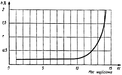
Fig. 4. Characteristics of the harmonic content factor at 1000 Hz
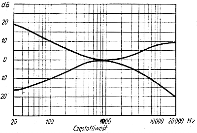
Fig.5. Frequency characteristics of the amplifier depending on the settings of equalizers