
Czesław Klimczewski, "Speaker power amplifier"
Radioamator 1952/11
Many schools, club rooms and radioamateur wheels have radio receivers but they lack amplifiers, which would enable the playback of programs by a larger number of loudspeakers installed in the rooms. For those amateurs a description of the power amplifier with the method of its assembly is given. The amplifier connected in a suitable way to the radio receiver will allow to obtain the necessary electric power for powering several loudspeakers with a total power of about 15 or 20 watts, depending on the type of radio tubes used.
Fig. 1 shows the schematic diagram of the power amplifier. We see on it that it has two tubes operating in the so-called push-pull system ("Push - pull"), powered by AC power from the electric lighting network.
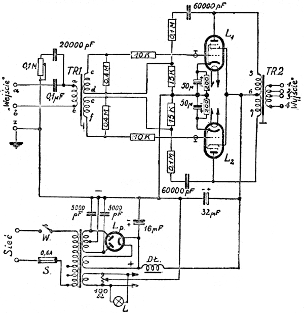
Fig. 1
The power amplifier tubes receive the low frequency voltage needed to drive their grids through the TR.1 transformer called "input transformer". This transformer consists of one primary winding and two identical secondary windings. Each of the secondary windings transfers the obtained voltage to the control grid of the corresponding tube. The primary winding has terminals connected to the input sockets of the amplifier in such a way that one of these terminals connects to one socket ("b") directly, the other to the other ("a") not directly but through a capacitor of 0.1μF . During the amplifier's operation, these sockets are connected to the radio apparatus, or to its additional loudspeaker sockets located on the back of the box or in the absence of them - with wires led out from the ends of the primary transformer winding attached to the loudspeaker in the radio receiver. The connection of the amplifier with the radio apparatus in the absence of these sockets in the apparatus for connecting an additional loudspeaker is given in Fig.7.
As mentioned above, the secondary windings are identical and have twice as many turns as the primary winding. The beginning (c) of one secondary winding and the end (f) of the other similar winding are connected through 10K resistors with legs in the tube bases (s1) assigned to the control grids. These resistors contribute to the correct operation of the amplifier by preventing any harmful interfering couplings or even preventing the reception of amplified programs. The other ends of the secondary windings, ie the end (d) of one of the windings and the beginning (e) of the other - are connected through 15K resistors to the earthed metal chassis of the amplifier. This chassis is connected to the Z socket, to which the ground wire is inserted.
For the last mentioned ends of the windings, in places connecting them with resistance 15K, 0.1M resistors are connected, which in turn connect to capacitors with a capacity of 60000pF. The bridge is made of 0.1M resistor connected in series with one another and capacitor with a capacity of 60000pF, which then is connected to a spring in a tube base having a contact with the foot belonging to the anode (a) in the tube - together with the 15K resistor. Thanks to this negative feedback, the amplifier more clearly reproduces amplified broadcasts resulting in less non-linear distortion. The amplifier is also less sensitive to load changes caused by different number of connected speakers.
The beginning and end of each secondary winding are connected with each other by a 0.4M resistor. These resistors align the frequency characteristics of the transformer, so that the quality of the broadcasts played by the speakers is very good
Because some of the radio receivers do not have tone control, so it was used in this amplifier. The tone change of the broadcasts is made by turning the potentiometer with the resistance of 0.1M switched in series with the capacitor with a capacity of 20000pF between the ending (a) of the primary winding transformer TR.1 and the earthed metal chassis of the amplifier.
Assembly wires connecting the springs in the tube bases (belonging to the control nets) with 10K resistors should be well insulated and arranged in such a way that they are as close as possible to the chassis, which will partially serve as an "anti-electromagnetic" protection against disturbing amplifier operation.
The feet in the tube bases corresponding to the tubes cathodes (k) are connected in the circuits of both tubes with the amplifier chassis or minus of the amplifier's power supply - through 200ohms resistors and 50μF electrolytic capacitors connected in parallel. Secondgrids (s2) of these tubes are connected directly to the positive voltage received from the anode power supply.
The tube anodes (a) are connected to a negative feedback bridge (capacitor 60000pF and resistance 0.1M) and to the primary winding of the output transformer TR.2. From the secondary winding of this transformer, acoustic frequencies are obtained to supply various types of radio loudspeakers.
Transformer TR.2 has two identical primary windings, and one secondary winding with taps, from which different voltages are obtained. The beginning of one primary winding ("5") connects with a spring in the socket corresponding to the anode of one tube, the end of the second primary winding ("7") is connected with a spring in a similar socket corresponding to the anode of the other tube. The end of the first winding and the beginning of the second are connected together and with the positive voltage wire from the anode power supply. The primary winding is actually one winding having a withdrawal from the inside (half the number of windings), thus creating two identical windings.
Going to discuss the diagram of the anode power supply, we can see from the diagram in Fig.1 that the AC power network is connected to two sockets marked "Network". One of these sockets is connected to the original winding of the TR.S power transformer through the "W" switch, the second - through the "S" fuse adjusted to 0.6Amp current. The primary winding of this transformer has a tap that enables the power supply of the amplifier with alternating current of not only 220V but also 110V. The secondary windings allow to obtain two anode voltages of 360V and also 4 or 6.3V (depending on the type of used rectifier tube). Anode voltages are obtained from a winding having a tap made of half of the total number of turns. This detachment connects with the metal base of the amplifier and creates the "minus" pole of the anode voltage. The end and the beginning of this winding is connected with springs in the tube base belonging to the anodes of the rectifying tube.
One of the 4V (or 6.3V) windings is connected with the springs corresponding to the cathode of the rectifying tube and serves to glow its heater. From one end of this winding we get the plus pole of the rectified anode voltage. The cable connected to this terminal is connected to the low frequency choke "DŁ" and to the "plus" pole of one electrolytic capacitor with a capacity of 16μF. The end of the "DŁ" choke winding is connected to the "plus" pole of the second electrolytic capacitor with a capacity of 32μF and with the cable supplying the amplifier with the anode voltage. Both "negative" poles of electrolytic capacitors are connected to the amplifier base, which also has a negative potential. The "DŁ" choke and both electrolytic capacitors form a filter that balances the rectified voltage, making the current similar to the DC current obtained from the anode battery.
The second winding 4V (or 6.3V) is used for heating the amplifier tubes and is connected to the appropriate feet in the sockets of these tubes, and - with the holder of the "L" signal bulb serving as an indicator that the amplifier is connected to the electrical network. At the time when the amplifier does not work and is not under the current - this bulb does not light up. In order to obtain a perfectly clean (without "hum") playback of amplified programs, the ends of this winding are also connected to an adjustable resistor with a 100ohms resistance. By adjusting the slider of this resistor, you can completely remove any "hum".
When mounting the amplifier, it must be remembered that the voltage supply wires for the tubes are well insulated and twisted in pairs. Twisting of wires will remove harmful electromagnetic field around them, which can affect the very sensitive circuits of the control grids of the amplifying tubes, causing interference to the received programs due to the strong hum of the current in the form of "buzzing".
Fig. 2 and 3 show the assembly diagrams of the power amplifier showing the connections to be made and the spacing of its components.
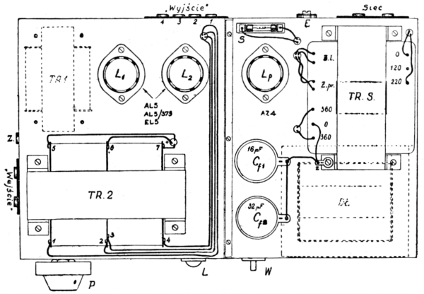
Fig. 2
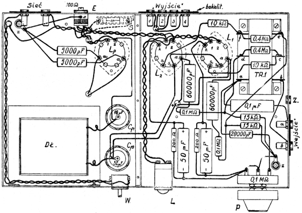
Fig. 3
It is important to properly arrange the transformers and the choke. This setting must be such that they do not interact with each other and can be achieved by appropriate spacing and correct orientation of the central column of each core. Regardless of this, the power supply should be separated from the reinforcement part of the amplifier by a sheet of iron. Failure to comply with the arrangement given in Fig. 4 may result in circuits strengthening the formation of parasitic couplings that prevent the operation of the amplifier.
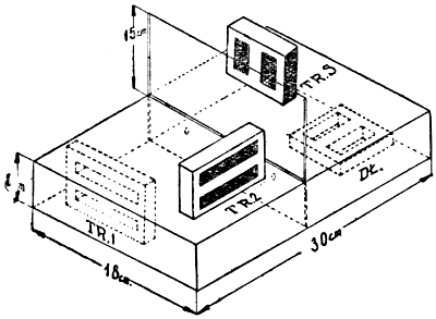
Fig. 4
Fig. 5 shows the connections of windings in transformers TR.1 and TR.2 in the case if these transformers are wound up by the radio-amateur.
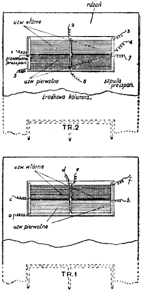
Fig. 5
Fig. 6 shows the arrangement of tube bases visible from the bottom for tubes series "E" - "steel" and for tubes of the Soviet or American type. Symbolically, individual electrodes have been marked on the drawings, which will facilitate the assembly of the amplifier, since the appropriate wires shown in the assembly diagram can be connected to another socket keeping the electrode markings to which they should be connected.
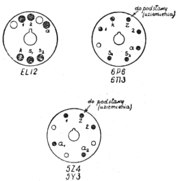
Fig. 6
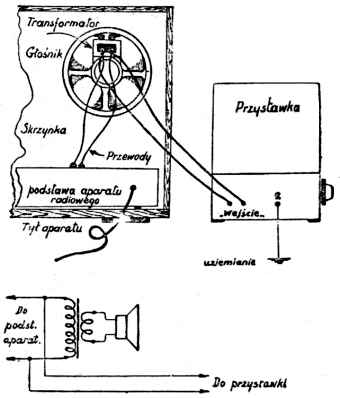
Fig. 7
Now, the data needed to make the transformers and chokes will be given.
The "input" transformer TR.1 is wound on a core consisting of insulated iron plates with a central section of the core column of 6 to 7 cm2. The primary winding of the transformer has 3000 turns wound with wire in enamel with a diameter of 0.15 or 0.1mm. The secondary winding has 12,000 windings wound with a wire of the same diameter as the primary winding. This secondary winding consists of two sections each with 6000 windings connected in series with each other. The origins and ends of each section are marked on the drawings and diagrams for easier connection.
The output transformer TR.2 is winding on a similar core but with a central section of the column 10 to 11 cm2. The primary winding has 1600 windings wound in two sections, 800 turns in each, the end of one and the beginning of the second section are joined together and form a tap derived from half the total number of windings. The wire used for winding the primary winding should have a diameter of 0.3 or 0.25mm and be insulated with enamel.
The secondary winding has 600 windings wound with an enamelled wire with a diameter of 0.5 or 0.4mm. Taps are led out from the turns of the 300th and 400th turns. These detachments and ends of the winding are connected to sockets marked 1, 2, 3, 4, from which the necessary voltages for powering the loudspeakers are obtained.
The TR.S power transformer is wound on a core with a center section of the column of 14 to 15 cm2. The primary winding has 760 windings wound in wire in enamels with a diameter of 0.6 to 0.5mm with a tap per 420 turns. The 220V network connects to the ends of the entire winding, and 110V - to its part containing 420 windings.
The high voltage winding has a coil wound in wire in enamel with a diameter of 0.15 to 0.12mm. The number of windings is 2600 with a tap from the center of the winding, i.e. with 1300 windings.
The windings for heating the amplifying and rectifying tubes are also wound with enamelled wire of 1.2 to 1.0mm in diameter. In the case of using 6.3V tubes in the amplifier, the number of turns is 20, and in the case of 4V tubes - only 13.
The low frequency choke L (filtering) is wound on a core with a column cross-section of 6 to 7 cm2. The number of coils is about 2500 wound using wire in enamels with a diameter of 0.2 to 0.15mm.
When winding the transformer and choke, it should be remembered that the wire should be laid evenly and quite tightly so that the coils lay next to each other and do not intersect, because then the enamel may scratch and short-circuit the coils, and thus damage the transformer (or choke) . The individual layers of the winding should be insulated with thin paper, and the individual windings between them with pressplan of the appropriate thickness (eg two layers of 0.2mm thick).
- Tubes:
- The 4 volt series:
- amplifying - AL5, AL%/375,
- rectifying - AZ4.
- The 6.3 volt series:
- amplifying - EL5, EL12, 6L6, 6P3,
- rectifying - 5Z4, 5Y3 (for heating of these tubes, the appropriate windings of the mains transformer should have not 13 but 20 turns).
- Indicator lamp - 6,3V/0,04A.
OTHER PARTS
- Amplifier chassis is made of iron or zinc sheet with a thickness of 1mm. Dimensions: 30cmx18cmx8cm. The chassis should have a bottom closed with a sheet of the same thickness and a partition inside and a wall ("screen") from the top according to Fig.4. It is also desirable that the amplifier should have a cover of such height that the tubes can be easily placed under it. This cover should be punched for the heat dissipation that is emitted during the amplifier's operation.
- 3 tube sockets.
- 9 sockets.
- A 2mm thick, pie-shaped plate for attaching sockets. (When mounting, make sure that the screwed-on sockets do not touch the metal base, as they will short-circuit them between themselves and the ground, so that the amplifier will not work).
- 1 holder for signaling bulb.
- 1 power switch.
- 1 fuse holder.
- 1 fuse 0,6A.
- 2 capacitors 5000pF/3000V.
- 1 capacitor 20000pF/1500V.
- 2 capacitors 60000pF/1500V.
- 1 capacitor 0,1µF/750/1500V.
- 1 capacitor 16µF/550V.
- 1 capacitor 32µF/550V.
- 2 capacitors 50µF/35÷25V.
- 2 resistors 10K/1W.
- 2 resistors 15K/1W.
- 2 resistors 0,1M/1W.
- 2 resistors 0,4M/1÷2W.
- 1 potentiometer 0,1M.
- 1 potentiometer 100omów.
- Mounting wire in needle or rubber with a diameter of not less than 0.8mm.
- Small assembly parts like tin, rosin, screws, nuts, etc.