Grzegorz "gsmok" Makarewicz
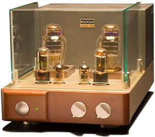
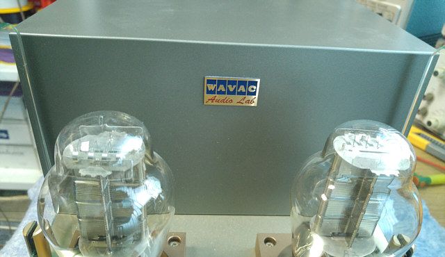
Very interesting and exclusive design. I must admit that until the amplifier hit in my arms I do not even realize that any copy of it is located in Poland. And suddenly such a pleasant surprise. I invite you to analyze the photographs showing construction details.
Specification
- Tubes: 12AT7, 6Y6, 300B
- Effective output power: 10W/kanał
- Load impedance: 8 (4/16)Ω
- Frequency rangei: 40Hz-50kHz
- Input sensitivity: 1.0Vrms
- Input impedance: 100KΩ
- S/N ratio: 80dB
- Power consumption: 250W
- External dimensions: 265mm (W) x 420mm (D) x 200mm (H)
- Weight: 17kg
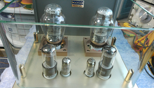
A cool glass cover. I like it. It is typical for WAVAC amplifiers. The disadvantage is that it is not in any way attached to the housing. The cover is just standing on the housing and delights the eyes of the owner.
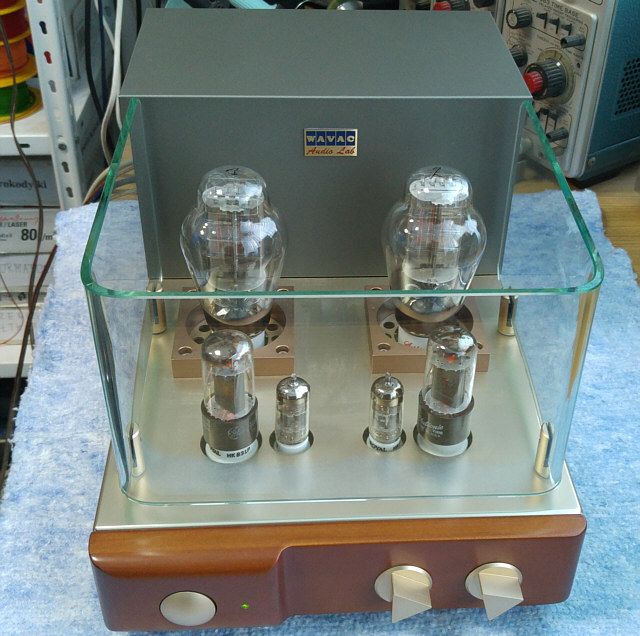
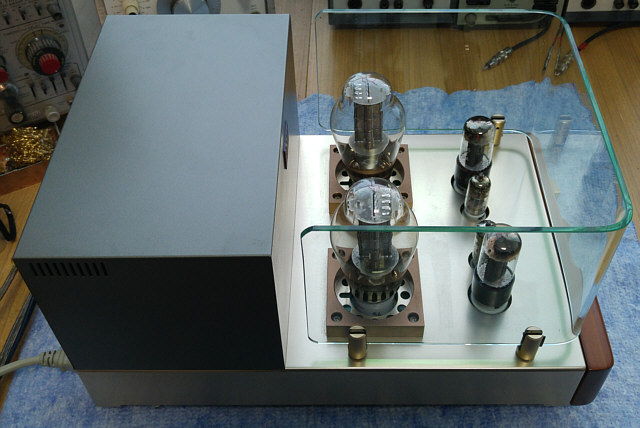
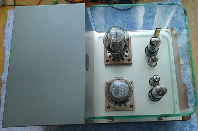
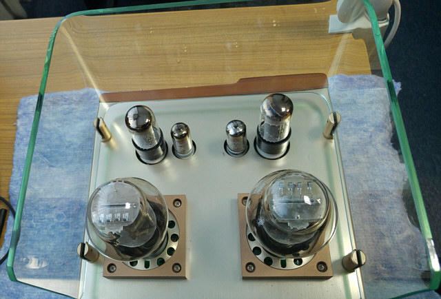
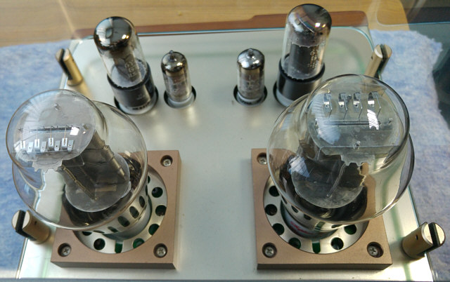
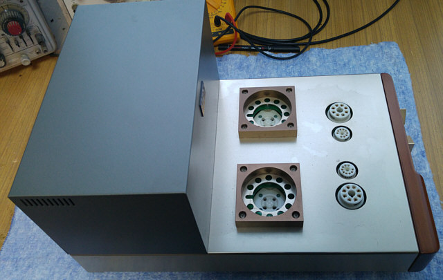
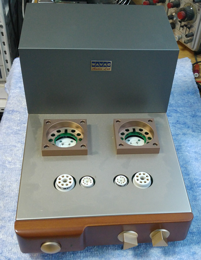
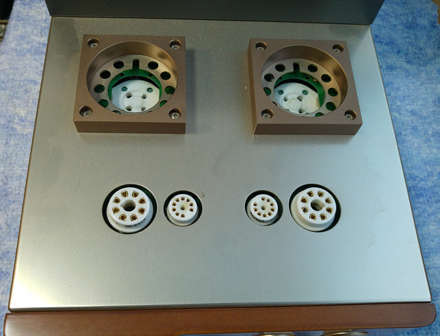
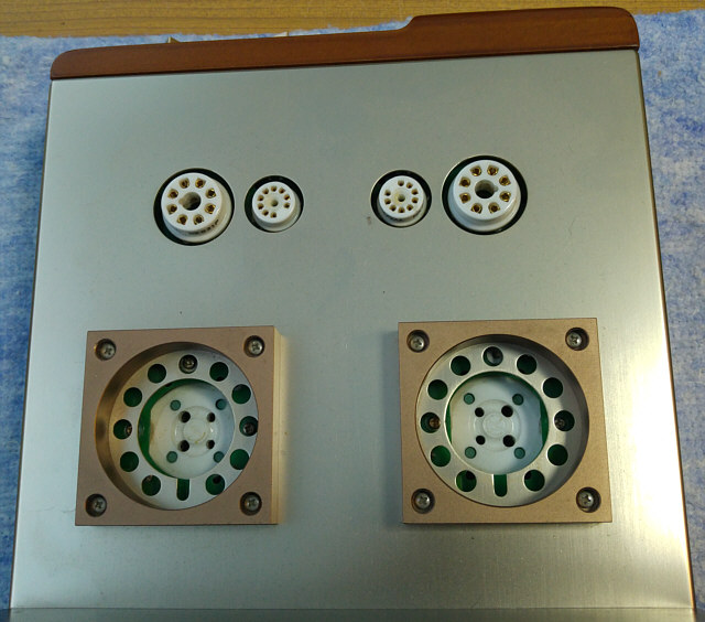
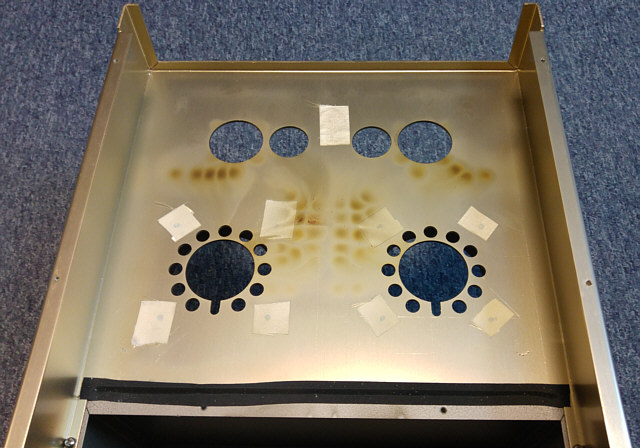
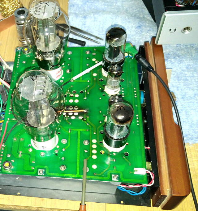
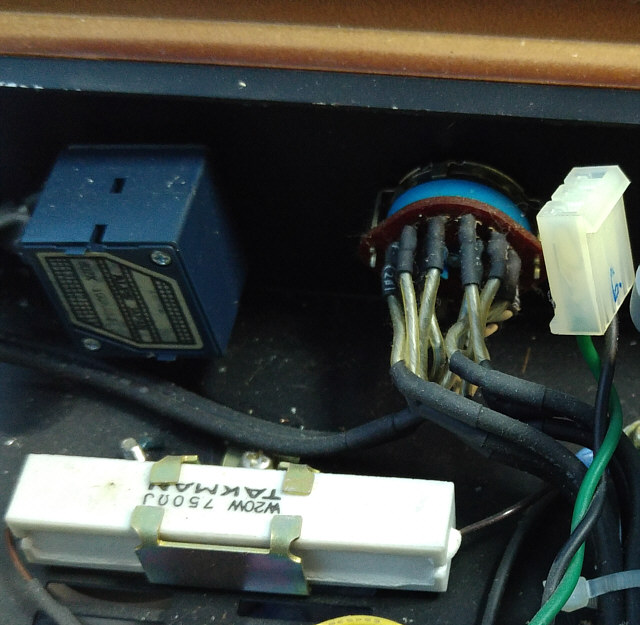
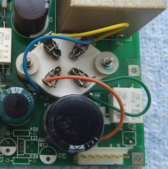
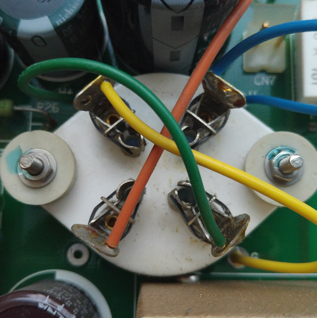
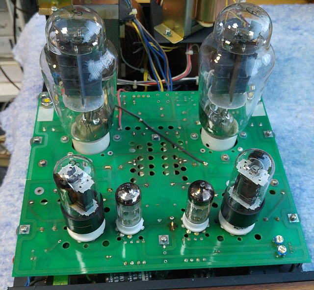
After removing the power tubes (300B) you can see how much effort was devoted to embellishing the tube sockets. Extra view!!!
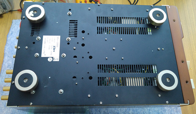
The feet have rubber shock absorbers so that no vibrations of the ground does not move to the inside of the amplifier.
Opening the housing is not easy and requires a lot of gymnastic skills.
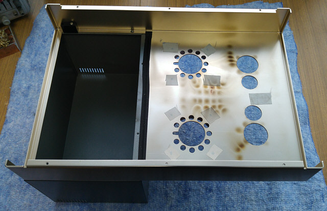
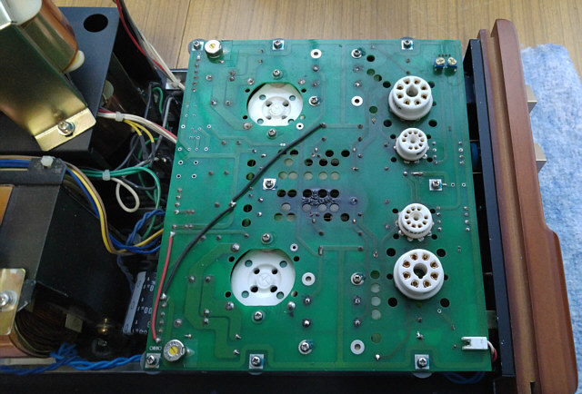
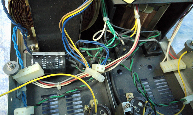
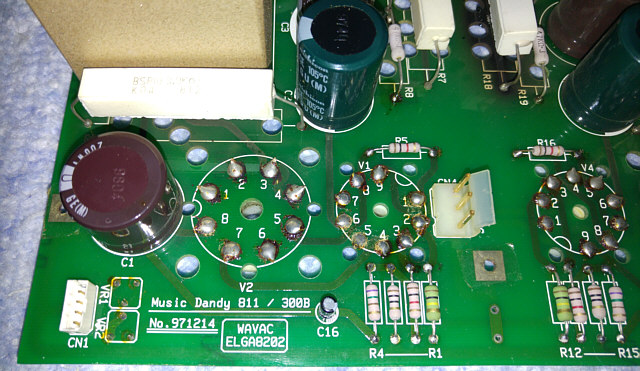
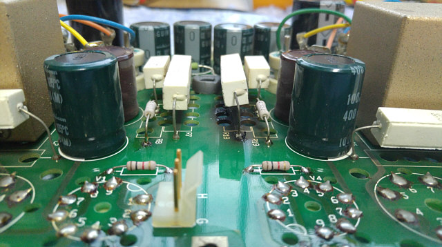
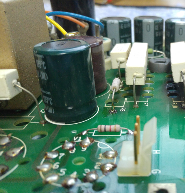
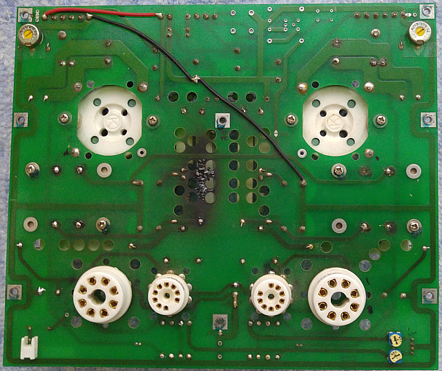
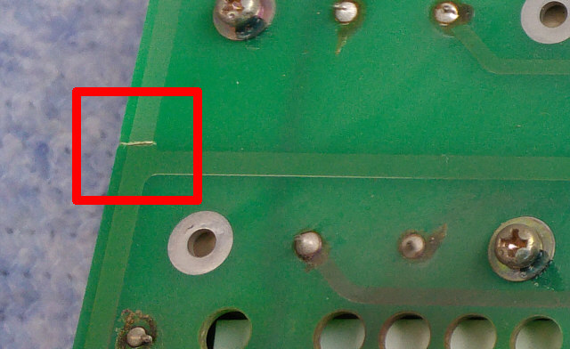
Ugly shade in the middle of the circuit board shown in the following photograph and other images is not an optical illusion - it's the reason because of which the amplifier came to me. Cause was admittedly prosaic, but it gave me a lot of trouble in locating it.
I have not found anywhere the schematic of WAVAC MD-300B. On several pages only information appears that the topology is similar to that used in the Shishido amplifier. Schematic of this amplifier based the 811A power tube is shown below.
And here is the result of my curiosity. For those interested in circuit details, schematic diagram of power supply and amplifier section drawn from nature is presented below.
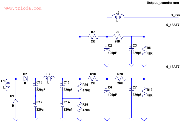
Like probably in all Wavac amps, there is no coupling capacitor in amplifier section. The 12AT7 is directly coupled to the 6Y6, which drives the 300B through an interstage transformer.
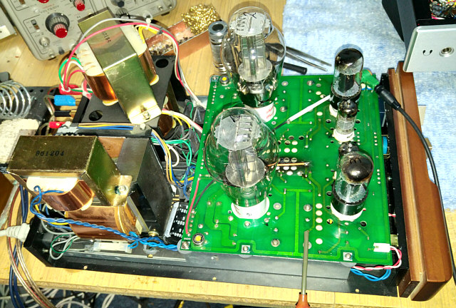
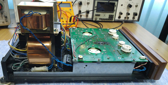
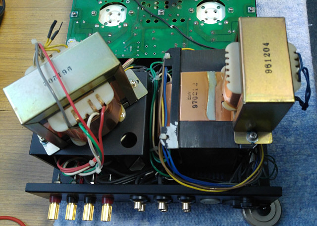
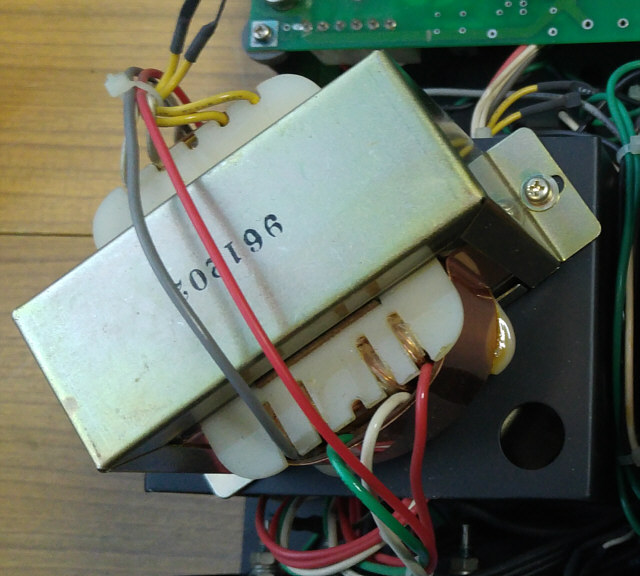
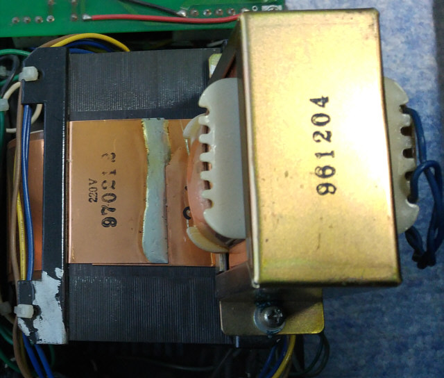
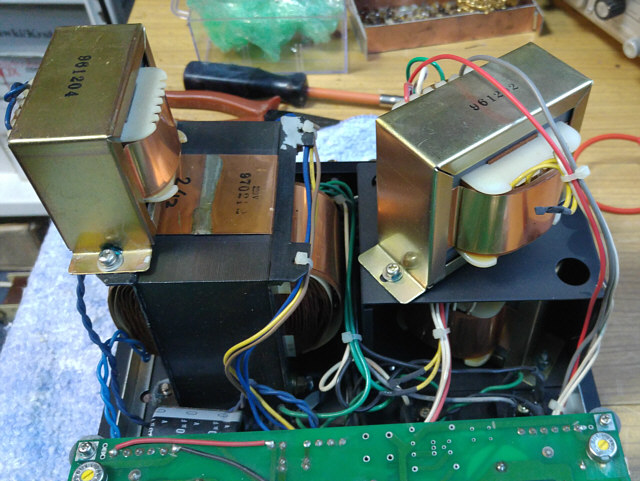
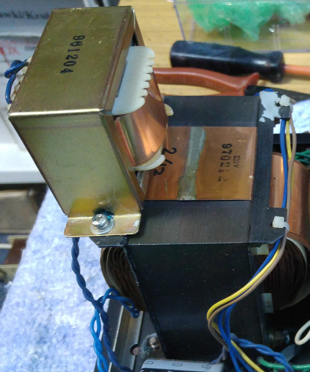
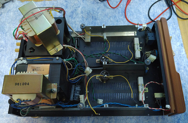
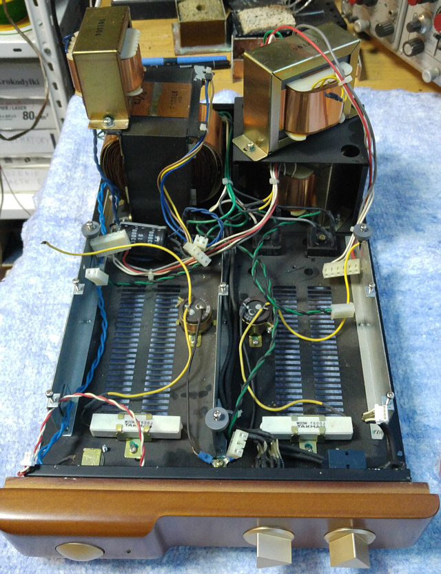
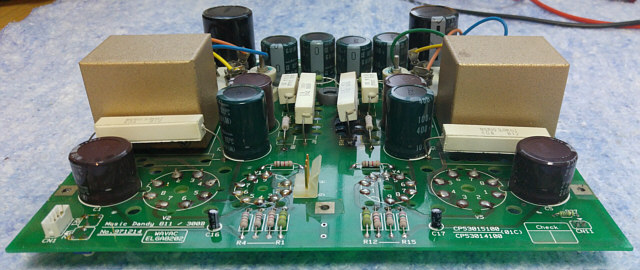
Side view shows the bizarre structure created with transformers and choke.
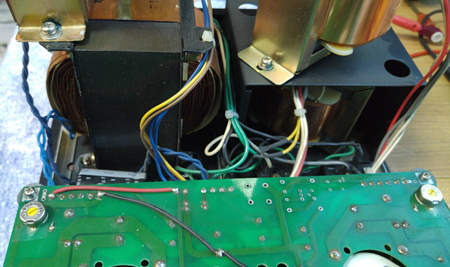
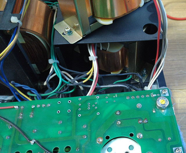
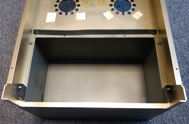
Interior view after removing the circuit board.
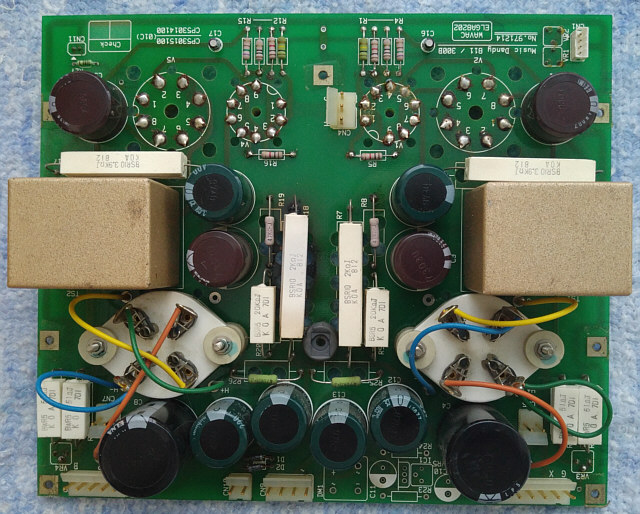
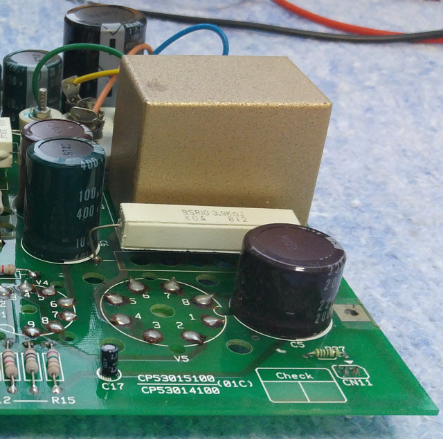
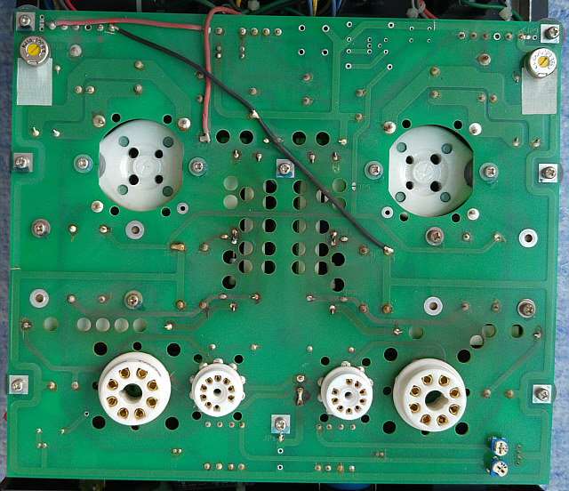
And here is the PCB with components.
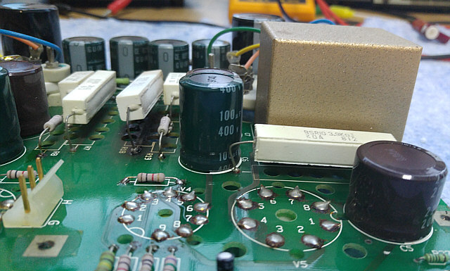
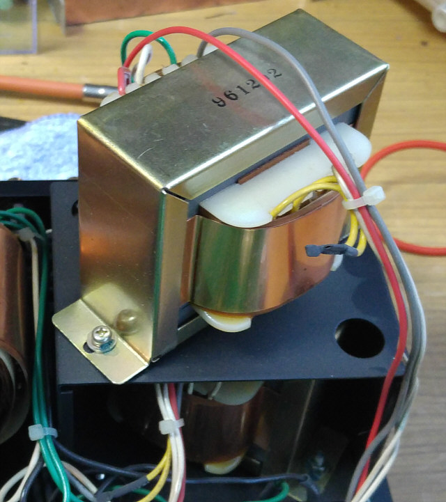
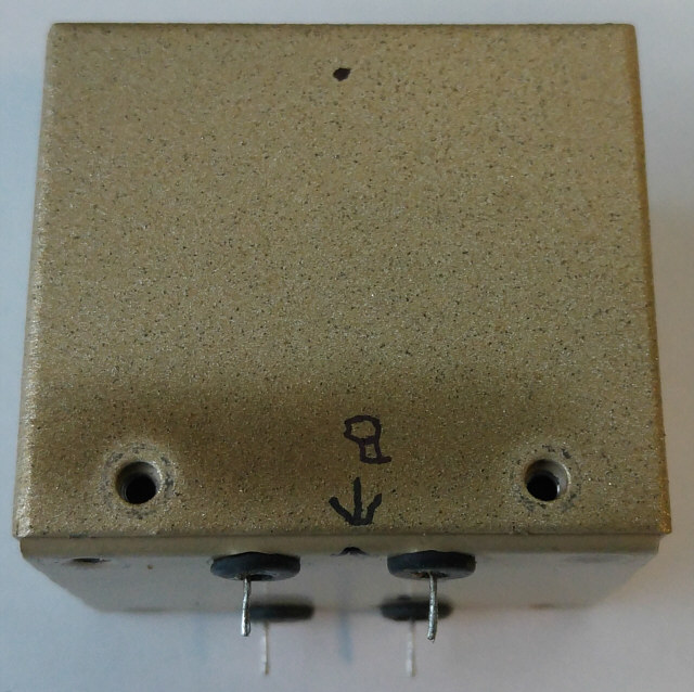
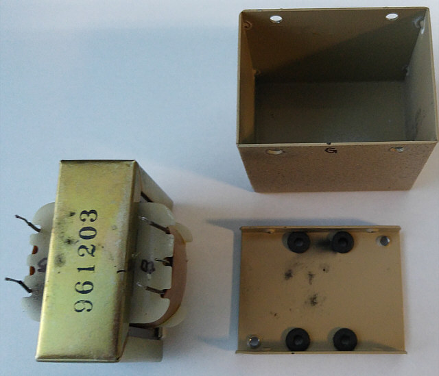
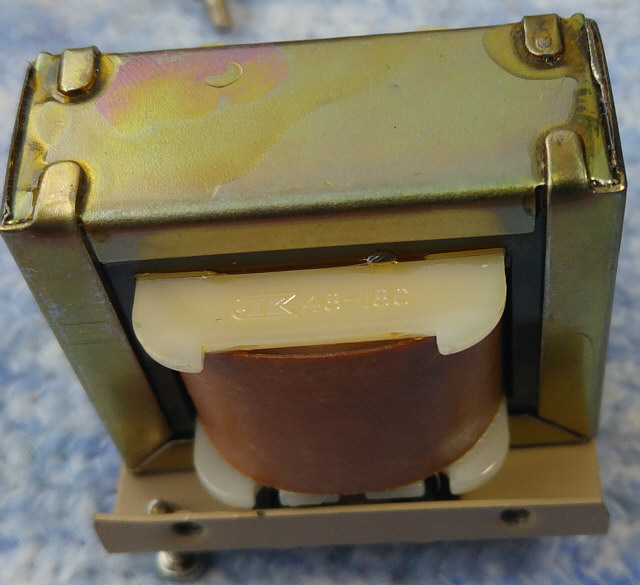
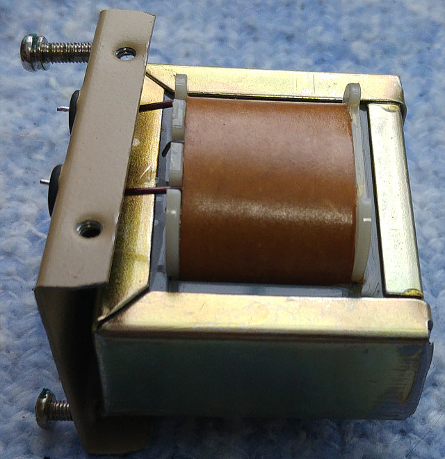
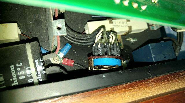
Interstage transformer placed in a solid box.
Updatedated 04.08.2016.
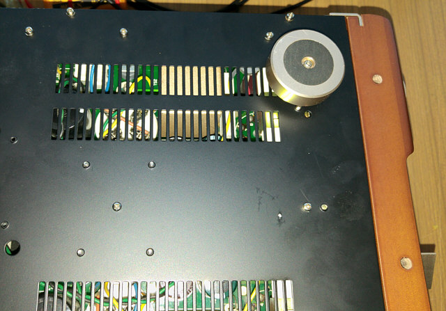
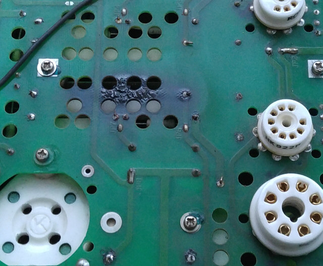
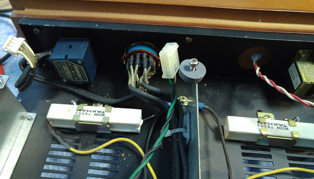
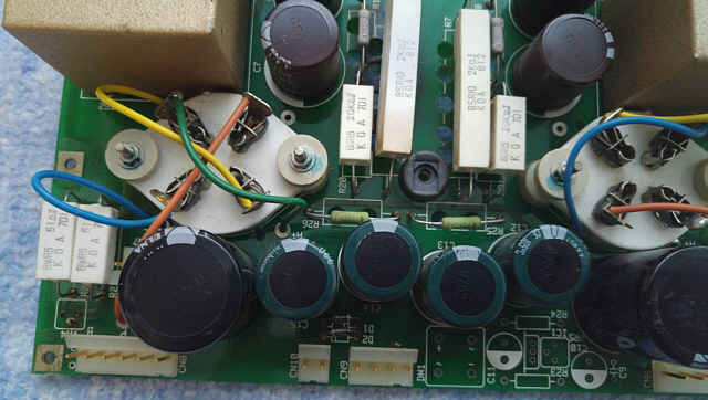
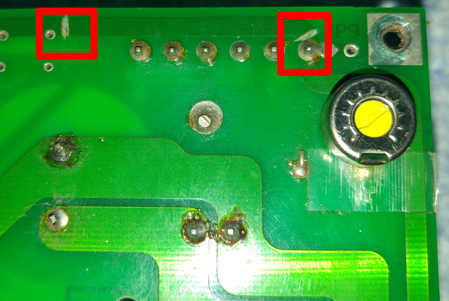
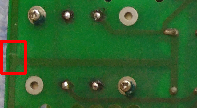
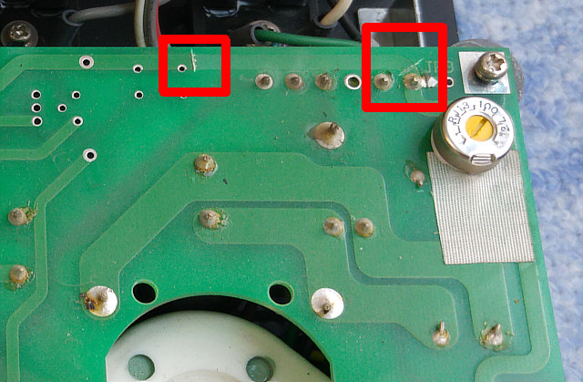
It took a few weeks and suddenly to my surprise and happiness I had the opportunity to familiarize with the second copy of the amplifier. I noticed some interesting differences consisting in places where someone (producer?) cut the ground path. This was done probably to eliminate hum. This "technology" does not put the producer in a favorable light (unless, that these "modifications" did someone already after selling the amplifier).
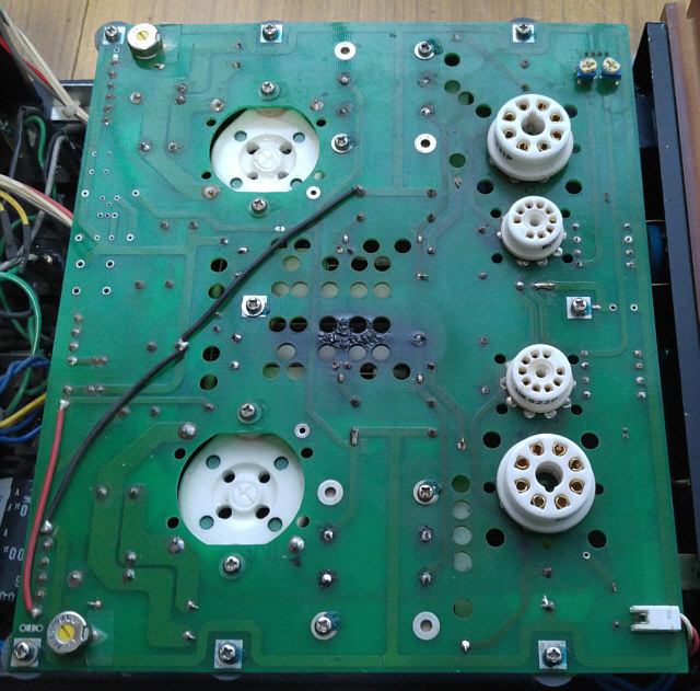
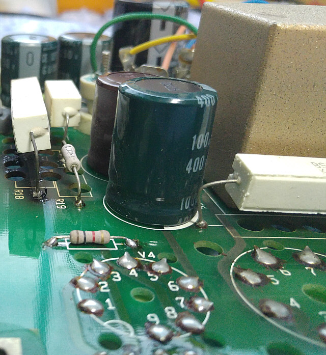
Let's see how it looks. At the beginning the general view of the PCB and enlarged fragments of cut paths of the first copy of the amplifier:
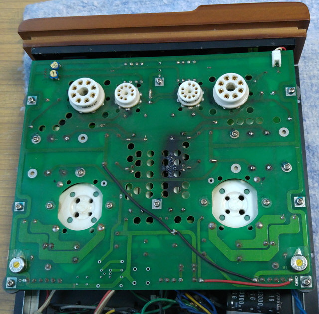
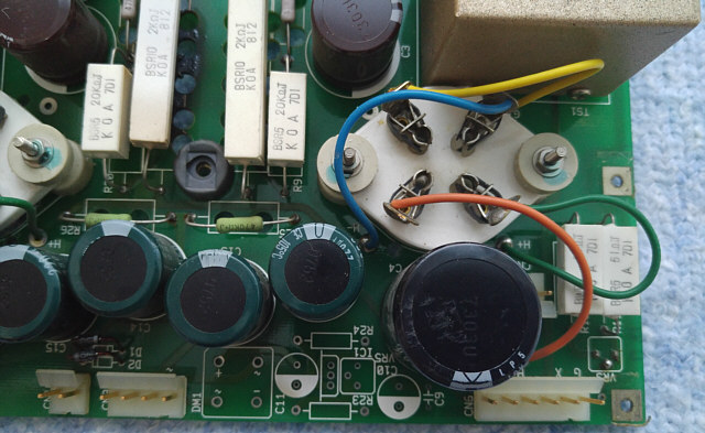
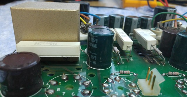
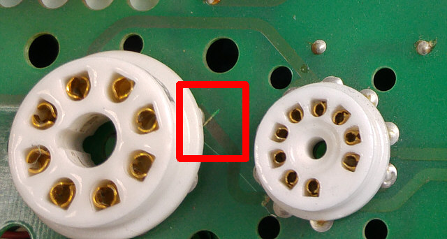
And now, for comparison some views of the PCB and the details of the second copy of the amplifier:
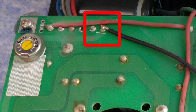
In order not to end the description in such a pesymistic way, I put two purely informative and uncritical photos below.
Written by Grzegorz "gsmok" Makarewicz
")
")
")
")
")