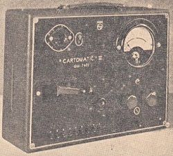
Device for testing electron tubes
(Radio dla techników i Amatorów, Październik 1949, Rok IV, Nr 10)
In our monthly magazine, we have not yet described an important and basic instrument, which is the practice of a radio amateur and radio technician - a device for testing electric lamps. Twice, however, such a device was described by our brotherly weekly "Radio i Świat", namely in 1945 No. 15 entitled "Instrument for testing the emission of electron tubes" and in 1947 No. 36/37 entitled "Instrument for testing electron tubes". Both of these apparatuses made use of the same principle, shown in Fig.1. The mains transformer has a secondary winding of the filament of the vacuum tube and some additional winding giving an effective voltage of up to 20 volts. The end of this winding is connected, through a limiting resistance of 500 ohms, protecting against the effects of possible short circuits or overloads, and a DC milliammeter - to the anode and other high-voltage electrodes of the tested electron tube. Other electrodes, such as the control grid, are shorted to the cathode, which in turn has a common point with one glow pole. When a vacuum tube is inserted into a suitable socket, a one-way current will flow through it after heating up and cause the milliammeter to deflect. The above mentioned descriptions are accompanied by tables of "normal" deflections of more electron tubes.
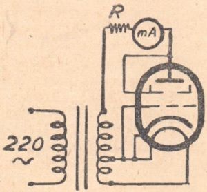
Fig. 1. Principle of operation of the most primitive device for testing electron tubes. All electrodes are connected either to the anode or to the cathode. A one-way rectification system is obtained, and the device measures the rectified current, which depends to some extent on the emissivity of the cathode. The shortcomings of this instrument are discussed in the text.
Instruments of the type shown in Fig. 1 operate on the principle of one-way rectification. Each electron tube, regardless of its proper purpose, is of course capable of rectifying, and it does so in a manner dependent to some extent on its "emission". Of course, there is no need to emphasize that the system in which we examine vacuum tubes is not even roughly similar to the conditions in which the vacuum tubes we use work in amplifiers, receivers, oscillators, etc. It even happens that we do not see a case at all any vacuum tube was ever supposed to work under such or even similar conditions.
But before we discuss these matters, let's consider what is the "emission" of a vacuum tube. Textbooks that talk about it say it's the cathode's ability to emit a certain number of electrons. In our practical view, we must supplement this by the fact that certain other electrodes are capable of making use of this emission, that is, by means of it, passing through the tube a certain current from an external source of voltage, alternating or direct. It must be immediately emphasized here that cathodes coated with oxides (mostly barium and strontium) do not have a clearly defined upper limit of "emission", that is, the anode current can increase with applied voltages until the electrodes overheat. Vacuum tubes with a tungsten, i.e. tungsten, pure or barium cathode have a specific emission limit. The "emission" fetish dates back to the seemingly long-forgotten times when electron tubes with such cathodes were in use. In fact, none of the devices for testing electron tubes test emissions, much less their "percentage". When demonstrating whether the electron tube gives this or that anode current, appropriate to the given conditions of its operation, we check, of course, that the filament or cathode is capable of supplying enough electrons for such a current to flow, but also to check the total emissivity of the cathode, Therefore, it is impossible to say whether the electron tube is worn out, or what are the prospects for its further life. Existing devices show only the anode current obtained from the electron tube under certain conditions specified for a given device, and here we can divide them into two basic categories: those that show a specific operating point, determined by the catalog data of the electron tube, so they provide the electrodes (anode, screen, grids, etc.) specific DC voltages selected for each type of tube. So these devices usually have several sources of direct current and numerous voltage taps. For ease of use, they usually use complicated switches or cards with punched holes. An individual card for each type of vacuum tube is placed in the appropriate window and contact plugs are inserted into its holes, which supply the electrodes with all the correct voltages. A large measuring instrument shows the "emission" or "percentage of consumption", which is actually, as we already know, the anode current corresponding to the set operating point. The milliammeter has a three-colored scale, and each section reads: BAD - POSSIBLE - GOOD. The device is not switched on immediately against the current in the final voltage system, but initially the electrodes are tested for short-circuits with others or breaks (fiber). In these tests, the measuring instrument plays the role of an ohmmeter powered by a direct voltage of several volts. This attempt is, moreover, completely mechanized, because the apparatus is switched on with a multi-position switch. At the initial positions, preliminary tests are carried out with all the electrodes in turn, and only at the last one - the proper quality test. At the penultimate position of the switch, the control grid of the vacuum tube receives some small additional negative voltage. This allows you to check whether the grid reacts to a change in voltage, so it is a complementary "dynamic" test, as opposed to a "static" test, which we consider checking the anode current. The proper operation of the electron tube is precisely the work due to the excitation of the lattice.
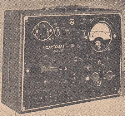
Photo 1. A modern device for testing Philips vacuum tubes. The card of the tested vacuum tube is placed on the side, the lever is turned to the left and all connections are made automatically. The nine buttons at the bottom, when pressed, give you all the trials you need. For other types of vacuum tubes there are appropriate adapter sockets.
The improvement and improvement of the same principle is the Philips camera. The cards here are made of a hard, quite thick material. They are inserted, pushed into a special slot, and then pushed with a lever located on the side of the box. As a result of this movement, 140 spring contact blades press against the plane of the Bakelite card, but of course only those that are opposite the holes go through and make contact, applying the required voltages to the appropriate electrodes, automatically and not manually as in the previously described model. There are eight buttons on the front panel, which are turned on successively and the vacuum tube is tested, initially for short circuits between the electrodes, and finally for goodness, or if you prefer - "emission".
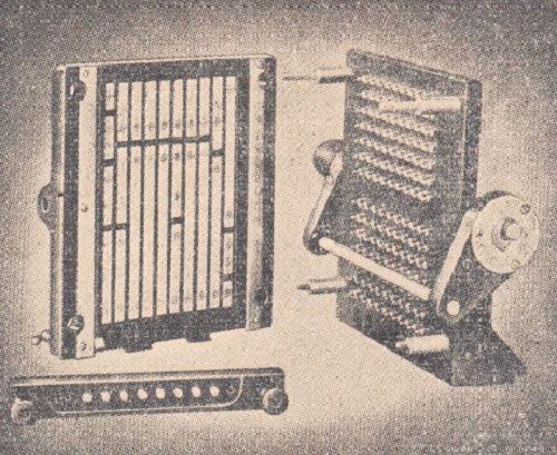
Photo 2. Layout for automatic connections. Voltage rails on the left, spring contacts on the right.
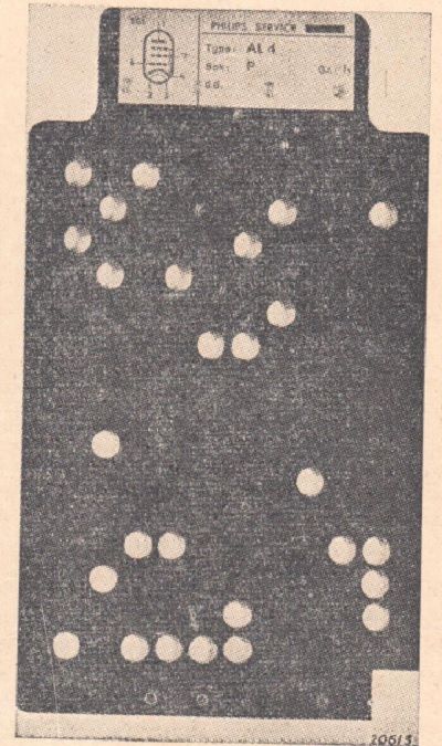
Photo 3. An example of a card for the AL4 vacuum tube. The holes allow only the contacts needed for the lamp under test to pass through.
Both of these devices are quite advanced and fulfill their task to a very large extent, without providing an answer to the fundamental, in the author's opinion, question: does the electron tube work well in its normal operating conditions? Other important matters, such as whether the electron tube does not hum or crackle, etc., etc., are not tested by any of the known apparatuses, for this they use, but probably only in laboratories or factories, large sets or testing cabinets. However, although the described devices still have some shortcomings, they are already very complicated. Making them with amateur means is impossible and I do not advise anyone to attempt it.
We would also like to emphasize that we do not in the slightest disregard the need or even the necessity to test whether the electron tube works with its normal anode current, which, as we have already pointed out several times, is popularly but incorrectly called the "emission" or "consumption percentage" test. However, that the test of the vacuum tube in active working conditions, i.e. what we have called the "dynamic test", was considered as equally important, is proved by the latest model of the Weston apparatus. And here we have the "BAD - POSSIBLE - GOOD" test, for the anode current. But besides that, by simply pressing the switch, we turn the circuit into a tube amplifier, with normal DC power supply. with a frequency of 5000 c/s. A circuit tuned to the same frequency of 5000 c/s is connected to the anode circuit of the vacuum tube and a parallel device, this time as a sensitive alternating current voltmeter. These conditions may not be completely consistent with those that the electron tube is to meet later, but if it passes both tests satisfactorily, the probability that it will have any shortcomings is negligible and you can use it with a clear conscience.
Building such a device, and especially its calibration, is all the more beyond the reach of a radio amateur. We only wanted to indicate the tendencies in the construction of the cameras in question. Let's move on to the extremely simplified system described at the beginning and shown in Fig. 1. It has a major advantage for the amateur: it is extremely simple, the simplest one can imagine. In addition, practice has shown that if we are to study the "emission" or the ability of the cathode to emit electrons, it is better to do it at low voltage rather than high. It turns out that if the cathode is weak, the detection of this weakness is made more difficult at higher voltage because high voltage tends to "pull" electrons from the cathode. On the other hand, low voltage can only use the supply of electrons that is created in the form of the so-called. space charge, i.e. an electron cloud around the cathode, and it is easier to show deficiencies in it.
A device in such a primitive design will often put us in an embarrassing situation: a "tested" electron tube with apparently good emission - does not want to work in the receiver. What will we learn about it if, for example, the grid is short-circuited with the cathode? The system in Fig. 1 shorts the grid with the cathode externally, so what will change in the anode current if it is also internally shorted as a result of damage? Nothing will change, we will receive no hint, no warning. The same can be said about the internal short-circuit of the screen with the anode, the same about the short-circuit of the cathode with the filament, so dangerous in universal vacuum tubes, especially rectifying ones (e.g. CY1, UY1, etc.). Besides, what does this tester tell us about the response of the grid to an applied voltage, DC or AC? No, definitely such a device, although of course it is better than nothing, is not sufficient for the most primitive workshop. After a few disappointments, we will lose faith in him and start looking for something better. Such a device of a higher category, which will give us, if not all, then at least much of the necessary data about the state of each vacuum tube - is described below. At the same time, it is sufficiently simple in construction, so that any radio amateur can make it. It is not, of course, free from some fundamental faults which we shall point out, but it is worthwhile and will render a service worth more than its cost and labor.
The schematic diagram of the sampler is shown in Fig. 2. The explanations there make it understandable, but we will add a few words of explanation. First of all, we have a limiting resistance of 400Ω 15 watts in series with the primary winding of the mains transformer: we always connect the instrument to the mains initially through this resistance. It will not prevent the milliammeter from deflecting, as it will only reduce it slightly - if everything is in order. If, on the other hand, there are faults, for example, short circuits, excessive current, etc., the resistance will limit the effects of these defects to a harmless value, both for the tube itself, as well as for the transformer, milliammeter, etc. When we see that everything is in order, we quickly skip the resistance and then we have a reliable current reading.
The basis, the center of our apparatus is the mains transformer. It must be very well made with a large number of taps for selecting the filament voltage. Since it is very difficult to make such a large number of taps, we advise you to order such a transformer from a reliable professional company. Here are his details:
- primary winding: 120V (wire ø 0.5) or 220V (ø 0.3).
- secondary: 0 - 1.25 - 2 - 2.5 - 4 - 5 - 6.3 (ø 1) - 13 - 16 - 20 - 26 - 30 - 35 - 45 - 50 - 55 - 60 - 90 - 110 - 120V (ø 0.4).
- general power 30 - 40 watts.
The second very important component is the filament voltage step switch. Only a very solid, reliable and durable component is suitable for our purpose, the number of contacts being 20, although this may be somewhat reduced at the expense of the choice of filament voltages. For example, the voltage of 2.5V (for old American electron tubes), then 16, 35, 55 and 120V can possibly be omitted in the first row, having previously looked in the catalog of electron tubes as to their choice. Contact hops can be short-circuited (neighboring contacts - during hops) due to the limiting resistance in the network cable. Turn on the filament voltages in turn, starting with the smallest one. The first position of the switch turns on the filament through a neon lamp at 120 volts. It is a test of the wholeness of the filament, because if it is broken or burnt, the neon lamp will not ignite. However, as experience shows, this is not a completely sure test, because sometimes a burnt fiber shows a certain flow, of the order of hundreds or thousands of ohms, and the neon lamp will not show this, it will light up without any noticeable weakening. There are not many such cases, however, in the glow circuit we provide sockets, normally closed, for possible connection of an external ammeter to check the glow current. If a broken fiber causes a short-circuit, it protects again the resistance in the mains cable.
We gradually increase the glow voltage, with pauses, patiently without unnecessary and harmful haste, with the mains resistance in the circuit. Here, anyway, we see a slight advantage of our system over the "card" ones, which necessarily switch on the heating voltage right away, which, as we know, is very harmful in universal vacuum tubes with high heating voltage and low current, so the same delicate filament. So when the glow voltage comes to normal, we wait until the milliammeter shows up and determines the current, and if we consider that everything is fine, at least in terms of short circuits or other anomalies, we switch to full mains voltage and after a short while the final current value in the milliammeter it will settle. We determine whether it is within the normal range or not and then we quickly make a few tests, namely: grid reaction test: the key (in the model, the telephone key, the so-called Kellog) switches the grid from pre-voltage zero, i.e. equal to the cathode, to a voltage of 6 volts variable, but selected in such a way that it comes in phase with the anode voltage. Thanks to this, the anode current increases, giving a clear and positive indication of whether and how the control electrode in the tube works and how the anode circuit reacts. We have already emphasized several times that this is a basic test, without which there will never be any certainty that the electron tube works. Of course, we emphasize that in our system the electron tube does not work in its normal operating conditions, because it is not powered by direct voltage but alternating voltage, and besides, its individual electrodes do not have a choice of voltages, as in the catalog, but only 0 - 6 - 120 volts AC. It works as a rectifying diode, as in the primitive system in Fig. 1, with the difference - that at a higher voltage, thanks to which various more or less dangerous damages can be more easily detected, and with grid control, active and effective even at alternating voltage anode and screen.
We wrote above that we determine whether the anode current is normal or not. Of course, this is not the current that is given in the catalogs of electron tubes. This value is specific to our working conditions. We can determine it best by comparison with good, reliable tubes, or by gradually testing more tubes and aligning the average. If, after a thorough familiarization with the device and its deflections, a new, unknown vacuum tube comes along, it can be assessed by comparing it with analogous ones of another series with similar properties. In any case, to define the so-called The so-called "emission percentage" in this device should be treated with reserve - I have serious doubts about other devices, too. Of course, with weak and worn-out vacuum tubes, their weakness will be revealed clearly and without ambiguity, but we put more emphasis here on the operation of the grid, and thus the work of the vacuum tube. As we shall see, the two go hand in hand.
Simultaneously with the construction of the device, we put on a few notebooks in which we diligently record the results of testing each vacuum tube, with any comments as to its behavior in the receiver or amplifier. Only in this way will we learn the properties of each of them, and the notes will be useful to us all the time. Let me give you one example: mixing tubes do not oscillate at short wavelengths. ECH11 and especially UCH11 have a particularly bad reputation in this respect. So we carefully note the deflections given by the triode part of these tubes (two: at zero grid and at 6 volts on the grid) and mark which of them did not oscillate at short waves. With a certain number of specimens, we will be able to determine with high probability in advance which of the tested vacuum tubes is good and which is bad, in this important respect. The "shift" of the anode current when 6 volts is applied to the grid is more important in this case than the quiescent current, because the operation of the grid primarily determines whether the electron tube will be able to oscillate in difficult working conditions at short waves. A similar situation is also observed in the operation of amplifying triodes, especially in combined vacuum tubes VCL11, ECL11, UCL11, loudspeaker pentodes, especially directly heated ones such as RES64, 964, AL1, etc.
If the electron tube is damaged, for example, there is a short circuit between the screen or the anode and the grid, then our milliammeter (direct current) will not show deflection, but the anode bulb will glow, the current of which is selected according to the supply voltage (120 volts) and the limiting resistance ( 1000Ω). Glowing of the bulb without tilting the device (the arrow trembles slightly around the zero position) is an indicator of a short circuit. If the grid to the cathode is short-circuited - there will be no upward shift of the anode current, a possible short-circuit can be investigated as we will give a little later.
Another important test is to determine the insulation between the cathode and the filament of indirectly heated electron tubes. In the model device, both of these tests are carried out by means of one telephone switch ("Kellog"), and in the normal rest position in the middle it connects the grid to O and the cathode to O. In the "away" position it shifts the anode current to include 6 volt on the grid, in the position towards itself opens, the connection between the cathode and O is broken. The anode circuit is thus broken and all or almost all of the anode voltage is deposited between the cathode and the filament. If the insulation is adequate, the anode current will drop to zero, if not, it will continue to flow in whole or in part. The examination of the cathode-fiber insulation is clear and unambiguous in this system, and the test voltage is properly selected. At a lower voltage, the influences that occur during operation will sometimes not appear, while at a higher voltage, even a good vacuum tube may be damaged.
In this way, any short circuits that may occur can be detected and fixed without harming the tube or any component of the tester. Every practitioner will admit that these tests are necessary.
We still have a test marked as a vacuum test in the instrument. Now, it is known that with a bad vacuum, a certain greater or lesser grid current flows at zero grid voltage. When a relatively large resistance (0.5 MΩ) is connected to the grid circuit by opening the button, due to the voltage drop on this resistance, a certain shift of its voltage occurs, this time in the negative direction. The anode current then of course decreases and from the depth of its decrease we know about the quality of the vacuum. This is a useful attempt, but of course not the primary one and does not give clear indications. Some loudspeaker tubes, for example, give a fairly significant drop in the anode current when the above-mentioned resistance is inserted into the grid, and yet they work perfectly well in receivers, in their obviously normal operating conditions, with negative grid pre-voltage. Despite that, the author got used to this test, because it gives a certain shift of the anode current downwards, increasing the set of information about the operation of the vacuum tube. Direct-heating electron tubes give almost no response to the "vacuum" test.
In the system we see one more switch, namely switching on the voltage to the anode either 120 volts or 6 volts. This lower voltage is used only for testing diodes, because firstly, high voltage can be dangerous for them, and secondly, at low voltage they show their possible shortcomings more easily. With the high voltage turned on by the 50 KΩ resistance, there is hardly a diode that does not show the norm, while at 6 volts, more than one turned out to be weak. This is, of course, an additional sample, created in the course of experimenting with various possibilities of the sampler.
We will now discuss the system in which the individual electrodes of the vacuum tube are connected to the sockets shown in the diagram in Fig. 2. These sockets have all the voltages intended for each possible electrode, they just need to be properly applied. Socket Z gives the glow voltage from the switch, O - ground, K goes to ground through the switch, so it is intended for cathodes, G goes either to ground or to 6 volts, so it serves grids, A gives anode voltage, finally D the same voltage but through a reducing resistance of 50 KΩ and is intended for diodes.
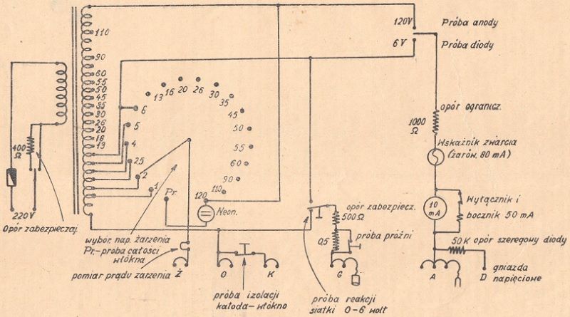
Fig. 2. Schematic diagram of the device. Sockets Z, O, K, G are double, A - triple, G has a cable with a cap, A - a cable with a tip. The vacuum tube is also tested in the one-way rectification system, but it is possible to test the insulation of all electrodes and the response of the grid to the anode current.
The model probe has seven sockets, the most common in our conditions, namely: the old five-pin (for example, for RENS 1284, RES 164, C 443, etc.), the old seven-pin (ACH 1, etc.), side eight-pin (for e.g. AL 4 , ECH 3 etc.), side small five-contact (for e.g. AB 2, VY 1), eight-contact for steel vacuum tubes (ECH 11, ECL 11 etc.), American eight-contact "octal" (for vacuum tubes e.g. 6A8, 6F6 etc.), and finally the American "loctal" (e.g. 7C5, 7B8 etc.), which is also used for the European "pressglass" series (UCH 21, UBL 21 etc.). In addition, there are few needed stands anymore, so installing them permanently is hardly justified, although of course it depends on the willingness and discretion of each instrument maker.
Letters and numbers are placed next to the contacts of each base. Getting acquainted with the principle of their marking is important, because it explains another property of our tester, namely the greatest possible flexibility and the ability to handle all types of vacuum tubes encountered. Each series of vacuum tubes generally has some uniformity in the arrangement of the electrodes. Some, for example, have heating always in one place, others have a cathode or metallization. These contacts, established once and for all, for a given socket and all associated electron tubes, are connected directly to the voltage sources, which are, as we already know, sockets marked with self-translating letters. So, where at the base contact we have the letter O (start of glow and ground), Z (end of glow, i.e. the voltage that we set with the glow switch), K (cathode) - these electrodes are inseparably connected to the mentioned points of the system. In addition, the G (grid) is attached to a flexible cable with a cap and is intended for all vacuum tubes, except for some old five-legged ones, which have an anode on top of the bulbs. For these vacuum tubes, a second flexible cable terminated with a tip and connected to A (anode voltage) is provided. We placed the letters O, Z and K inside the circles marking the sockets to indicate that these are internal, permanent connections.
Numbers from 1 to 7, located outside the rims marking the sockets, refer to terminals that do not have fixed destinations and receive various potentials depending on the type of electron tube. We led them outside in the form of flexible, several-centimeter cables, preferably in different colors, terminated with banana plugs in the same colors. These plugs are inserted into the socket that will provide the electrode with the proper potential, and the sockets are multiplied, because we supply the same voltage to the anode and the shield. In some types, there are two or more grids, etc.
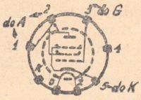
Fig. 3. Example of testing a vacuum tube: AL4. By manipulating pins No.1, 2, 3 and 5, all electrodes get the correct voltages and connections. The glow is permanently attached in this socket, you only need to set the switch to the correct voltage, here 4 volts.
The principle of operation of the device and its capabilities are best explained on the example in Fig. 3. There we have a system of electrodes of the AL4 vacuum tube. We see that the anode is attached to plug 1, the shield to plug 2, the grid to 3, the cathode to 5. So we take these plugs one by one and insert them into the appropriate sockets, giving this vacuum tube all the power it needs to test the voltage. We do this before turning on the power and after completing this operation - we check again to be careful if we haven't made a mistake. Then we turn on the power, of course through the safety resistance and look at the neon lamp, which should light up, because on the first contact of the switch it just shows the whole filament. Then, slowly and carefully, we jump over the contacts, watching the incandescence of the electron tube and stop at 4 volts of glow. Now you have to wait a while until the electron tube warms up and the milliammeter starts deflecting (the shunt should be connected, the sensitivity of the device is 50 milliamps). If there is nothing suspicious, switch the key to full supply voltage and perform the above-described tests on grid sensitivity, cathode-fiber insulation and vacuum. The values to which the milliammeter should deflect are given in the table below. They were obtained by diligently noting the results achieved with all the electron tubes. For this purpose, the author has four notebooks, where each series of vacuum tubes has its easily accessible chapter at the beginning or end of the notebook. In the upper corner, the type of vacuum tube or several very similar types (e.g. EF5 and EF9, etc.) are marked. Under each type, the filament voltage is given, which is especially important in the case of universal vacuum tubes, where it is not included in the label of the vacuum tube. Right next to or below the inscription, there is a plinth of a vacuum tube with letters and numbers taken from Fig. 4, immediately indicating where to insert the banana plugs.

Fig. 4. Electron tube sockets used in the model apparatus, together with markings necessary to make fixed connections (O, Z, K) and numerical variables 1 - 7. All the same numbers or numbers are connected to each other and each common rail with the appropriate system point.
For complete confidence and efficiency, the same thing is repeated in words next to it, so again for our example with the AL4 vacuum tube:
1 and 2 to A, 3 to G, 5 to K.
The plug-in system allows for various additional trials. For example, by removing plug 1 from the AL4 vacuum tube, we check the anode interaction (very weak here, the screen consumes all the current). Plug 2 will allow you to check the screen separately.
Besides - something extremely important - double vacuum tubes can be tested completely separately, each separately. Take for example the triode - ECH4 hexode. Here's our recipe:
Triode - 3 to G, 5 to A.
Hexode - 1 and 2 to A, 4 to G.
By examining both electrode systems independently, we can determine whether, for example, a triode is not weak with a completely good hexode. In the primitive system shown in Fig. 1, such an electron tube, examined as a whole, would certainly have a good "emission", "100%" and the result? - the receiver does not play on short waves and our radio technician is looking for a defect, e.g. in the coils, the switch and God knows what else.
By manipulating the plugs, there is no short circuit that cannot be positively detected, except for the automatic checking capabilities.
Broken leads of the electrodes can also be located. Let's take our AL4 again. If we remove the plug 2, we will turn off the screen. The anode current will drop very significantly. So when we have an AL4 lamp with a similarly low current, you need to remove the shield plug 2, if the anode current does not react - proof that the shield is broken and you should check it in the base. Once the damage has been checked, it can sometimes be repaired. We will detect the unresponsive grid or anode in the same way.
If we are to examine a vacuum tube, the base of which is not mounted in our instrument, it is quite easy to deal with in this case as well. Using cables terminated with crocodile clips on one side and banana plugs on the other, connect the electrodes of the vacuum tube to the appropriate sockets, using the plinth arrangement according to the catalog. Of course, this must be done very carefully, preferably with the help of another person. In this way, the author studied, for example, Loewe's multiple vacuum tubes.
The device allows for one more thing, namely the test of electrolytic capacitors. To do this, put the AZ1 or AZ11 vacuum tube into the socket, turn on the power supply, turn on the lamp and connect the capacitor between plug 1 (minus) and socket A (plus). The milliammeter will swing rapidly (sensitivity reduced to 50 mA) to about half scale, depending on the capacitance of the capacitor, then slowly begin to decline. You can then increase the sensitivity of the milliammeter by disconnecting the shunt and observe, after a while, the deflection of the instrument's arrow. With good capacitors it is below 1 mA. There is no danger in this test, even if the capacitor is shorted, provided of course the milliammeter is set to 50 mA. In the event of a capacitor short-circuit, the milliammeter will show as much as the used rectifying tube, switched on normally.

We emphasized that it is very important to have notebooks with our device, in which we will record the results of the tested vacuum tubes. So, for convenience, we will give an average table of the series of results, which will allow the contractor to get an idea of the quality of the tube at once, without waiting for more experience. This is an excerpt from the author's notebook, which we want to share with the Readers. The table is arranged by type of vacuum tubes and in alphabetical order. Of course, it is not complete, especially when it comes to American vacuum tubes, but it serves as a beginning and model and is subject to supplementation.
(The table will be given in the next issue - shown below)











Next to the type of the vacuum tube, we provide the filament voltage, the type of the vacuum tube, then the connections of the electrodes to the appropriate voltages, i.e. simply to which socket the plugs numbered from 1 to 7 should be inserted. Then the anode current is marked at rest and increased as a result of pressing the voltage shifting key mesh. At the time of switching on, we always shunt the milliammeter to 50 mA and when its deflection is less than 10 mA, we turn off the shunt.
We always press the cap corresponding to G on the tips of the vacuum tubes. With the few tubes where the anode is at the top, it is specially marked.
Instrument design
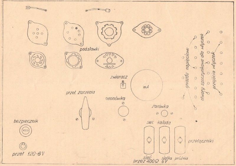
The entire instrument with all components and connections is assembled on a bakelite plate. With a greater density of elements, these sizes can be slightly reduced for the benefit of the portability of the apparatus. The model used the existing board in its entirety, and also made a mistake, due to habit, that the sockets of the vacuum tubes were moved apart, forgetting that more than one vacuum tube is not possible here. The sockets of the vacuum tubes can be placed tightly, one next to the other.
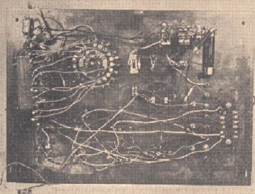
Photo 4. Device for testing electron tubes from below.
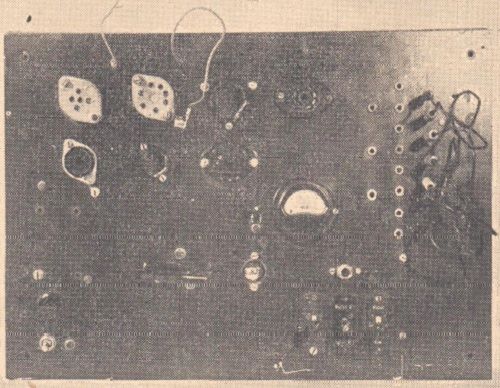
Photo 5. Device for testing electron tubes - top view.
When making the device, the parts should be carefully positioned, analyzing their position and the necessary space for a long time. It's better to think three times than to break the record once. Because the elements from which the radio amateur will assemble the device will not be the same as in the model, we do not give their exact dimensions. However, the layout of the elements, as in the model, passed the exam and turned out to be convenient and practical.
The front panel is matched with a wooden box on which the panel rests and to which it is screwed. The depth of the box depends on the height of the mains transformer as the largest component.
Connections
The connections are basically shown in the diagrams, but require a few words of explanation. We basically have two layouts to do. The power supply system in Fig. 2, in which there are probably no doubts, and the proper system, i.e. the sockets of the vacuum tubes that we will be examining, from Fig. 4. The ends of the sockets of the vacuum tubes with the markings O, Ż and K (located inside the circles ) connect with each other and common "rails" - with properly marked voltage sockets. The ends of the sockets marked with numbers from 1 to 7 are first connected to each other, and each again to a rail with a banana plug bearing the corresponding number. We will connect these terminals with voltage sockets by inserting the plug where the type of vacuum tube tested each time requires, according to the table.
Connections should be made with insulated wire, preferably in a different color, very carefully insulating and soldering.


