Bogusław Teichman, "2x8W stereo tube amplifier"
Radioamator i Krótkofalowiec 1972/07
Intermediate radio amateurs may be interested in the description of a stereo amplifier with good parameters and not a high construction cost. Here are the technical specifications of the amplifier:
- output power: 2 x 8W
- frequency response: about 40÷16000Hz
- sensitivity: about 120mV
- load resistance: 16ohm
- separate regulation of high and low tones.
Due to the lack of instruments, no distortion was measured, but with full control of the amplifier they were not noticeable. In principle, the amplifier had to meet two conditions: maximum good parameters and minimum costs. The elements used are typical, easily available; transformers and chokes should be made on their own.
Description of the amplifier (one channel)
In the preamplifier, half of the ECC82 triodes were used. It is useful due to the large input resistance, which has a positive effect on the sound controller. The controller's system is conventional. 1M potentiometers (type SP-3) are mechanically coupled together and the tone control (including gain) takes place simultaneously in both channels. The power amplifier operates in the push-pull circuit in the AB class. In order not to complicate the construction of output transformers, the "ultralinear" system was abandoned; this did not introduce any major deterioration in parameters. The phase inverter works in a cathode follower system. A 50-ohm potentiometer connecting cathodes to the ECL86 pentodes serves to equalize the anode currents in both tubes. The schematic diagram of the amplifier's layout is shown in Fig.1 (it includes one channel). The second channel is identical.
Fig.1. Schematic diagram of one amplifier's channel
Output transformers were wound on cores made of EI type mains transformers with a central cross-section of approximately 9cm2. In the center of the body a thin textolite baffle is glued, which divides the body into two halves. The method of winding windings is shown in Fig.2.
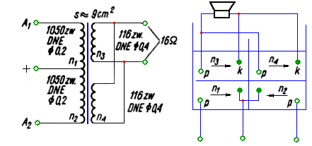
Fig.2. Way of winding of loudspeaker transformers
The arrows indicate the winding directions. The windings were isolated from each other with the "Tixo" adhesive tape. The ends of the windings were soldered to the soldering strip attached to the transformer. The method of winding the transformer (resignation from the ultraliery system) simplified its structure somewhat, however it caused the frequency cut above 16kHz. Nevertheless, it seems to be irrelevant at home.
The power supply (fig. 3) was made in a two-terminal rectifier system with two DK63 diodes. Due to the relatively high current consumption, it was not possible to use selenium rectifiers in the bridge system, or even two connected in parallel. The choke was wound on the core of a loudspeaker transformer with typical dimensions (cross-section 3.5 ÷ 4 cm2). The winding was wound to fill the body (approximately 500 rows). As a control lamp, a 220V neon light switched on the primary side of the transformer was used. The glow coil is balanced with an adjustable R23 resistor.
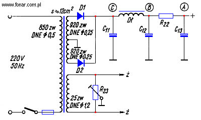
Fig. 3. Schematic diagram of the power supply
As the output load, two series-connected broadband loudspeakers (commercially available 8-YEAR / 5W Yugoslav speakers) in housings 50x40x25cm made of plywood with a thickness of 15mm were used.
The connecting systemt of both channels (not shown in the diagram) was used on the input, realized by means of a key switch. This system is needed when using an amplifier in a mono system. The wiring diagram is shown in Fig. 4. Attention is drawn to the way the system is connected - this is very important when playing from a monophonic tape recorder.
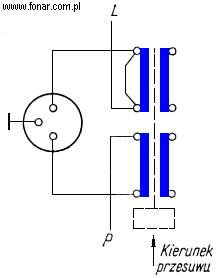
Fig. 4. Switch shorting inputs
In most cases, the authors publishing stereo amplifier circuits provide for a monophonic jumper in the form of short connection of the input jacks of both channels. This is not appropriate because the tape-recorder connected to the recorders is equipped with WM-3 three-pin plugs, with one foot connected to the ground, the other with the "recording" cable and the third with the "reproducing" cable. With the connection of such a monophonic tape recorder with a stereo amplifier and setting the tape recorder to "read", the tape's ground is connected to the amplifier's ground (ie in order), the "reproducing" cable is connected to one channel of the amplifier, and the "recording" cable - with the second channel . But during the reading, the "recording" cable is shorted to the ground inside the tape recorder (its type switch). This results in either the operation of one amplifier channel (with open sphincter) or the failure of both channels (with the sphincter closed). The thing is, it just has a channel (or channels) to ground. The sphincter shown in Fig. 4 takes into account this state of affairs.
The new stereo adapters are equipped with 5-pin plugs, in which the wires are soldered slightly differently than in the three-pin plugs, therefore a second input socket was connected in parallel, accordingly changing the method of soldering the channel inputs.
List of components for one stereo channel
- Resistors
- R1, R7 - 2,2M/0,1W
- R2 - 2,2K/0,1W
- R3 - 100K/0,25W
- R4, R6 - 100K/0,1W
- R5 - 10K/0,1W
- R8 - 4,7K/0,25W
- R9 - 510K/0,25W
- R10 - 1M/0,25W
- R11, R12 - 68K ± 1%/0,1W
- R13, R14 - 470K ± 1%/0,1W
- R15, R16 - 1K/0,1W
- R17 - 120/1W
- R18 - 50/1W reg.
- R19, R20 - 120 ± 1%/0,1W
- R21 - 47K/0,1W
- R22 - 10K/0,5W
- R23 - 120/1W reg.
- Capacitors
- C1 - 5µF/250V
- C2 - 0,047µF
- C3 - 2,2nF
- C4, C7, C8, C9 - 0,022µF
- C5 - 150pF
- C6 - 1,5nF
- C10 - 100µF/25V
- C11 - 100µF/350V
- C12 - 50µF/350V
- C13 - 20µF/350V
- Diodes
- D1, D2 - DK62
- Potentiometers
- P1 - 500kohm, lin.
- P2, P3, P4 - 1Mohm (P2, P3 - lin., P4 - log.)
- Transformers and inductor as described.
- Speakers 2 pcs - 5W, 8ohm (for one channel)
Literature
- P.Masewicz - "Radiotechnika dla praktyków i amatorów".
- A.Witort - "Elektroakustyka dla wszystkich".
- Mies. "Radioamator i Krótkofalowiec" nr 4/1969 i 5/1970.
")
")
")
")
")