Low Frequency OTL Amplifier
L. Kononowicz, Candidate of technical sciences (translation A. W.),
Radioamator 1959/11
In recent years, both works in the Soviet Union and abroad have been carried out on the construction of devices (including audio amplifiers) providing amplification and reproduction of sound with little distortion. In the initial stages of low frequency amplifiers, due to the low signal voltages occurring there - non-linear distortions are small, and frequency distortions can be lowered by choosing the appropriate values of the amplifier elements. The largest distortions arise in the output stage of the amplifier, the main cause being usually the output transformer. The output transformer limits the range of the frequencies to be reproduced.
To extend the frequency response to the smallest frequency, it is necessary to significantly increase the inductance of the primary winding of the transformer, which, however, causes an increase in leakage inductance limiting the frequency response in a part of higher frequencies. The dependence of the magnetic permeability of the transformer core on the value of the current flowing through the winding induces non-linear distortions.
One of the basic ways to reduce both frequency distortion and nonlinear distortion is negative feedback. An excessive increase in the depth of feedback is not possible because the phase distortions occurring at the ends of the reproduced frequency band. Phase shifts reduce the stability of the amplifier's operation and can even cause its self-excitation. In order to improve the phase characteristics of the amplifier, we strive to eliminate elements that cause phase shifts. One of such elements is the output transformer.
If we take into account that the output transformer is a fairly expensive component, it will be quite understandable for constructors to develop systems of output stages of low frequency amplifiers without an output transformer. When using speakers with 5-10ohms coil resistance, it is quite difficult to achieve this goal, because in order to obtain 5-10W power, the output tubes would have to provide flow through load a current of 1-1.5A. Developing such tubes is a difficult task and therefore a better solution is to increase the resistance of the voice coil of the speaker to 400-800ohms. With such a resistance, the construction of amplifiers without output transformers is quite real. The most popular solutions are based on the so-called series-pushi-push system. The description of this arrangement is the subject of this article.
In ordinary push-pull circuits (Fig. 1a) the load R consists of two parts connected in series. If the load is a voice coil of a loudspeaker with high resistance, it should have Rob resistance, lead from the center point, and also be insulated from the amplifier's ground.
Parts of load with Rob/2 resistance can also be connected in parallel (Fig.1b); in this case, the resultant load resistance will be equal to Rob/4. The central outlet is unnecessary, but two power sources are necessary in such a system. Since the constant components of currents flowing through each tube are the same, both power sources can be replaced with one, as shown in Fig. 1c. In this case, only the variable component of the anode currents of the tubes flows through the load, so that a separating capacitor can be used and one of the load terminals can be grounded.
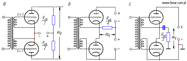
Fig.1. Different push-pull stages
The amplifier built according to the circuit of Fig. 1c is just a series-push-pull amplifier. Its advantages in comparison with the normal push-pull system are: four times less resistance of the load, elimination of the central outlet, the possibility of earthing one of the load clamps. These features of the system make it easier to use loudspeakers with high resistance as the load on the amplifier tubes.
The inconvenience of the series-push-pull circuit is the necessity of doubling the anode voltage (the tubes are connected in series for a fixed component). In order to construct an amplifier without an output transformer with the most frequently used anode voltages (250-300V), special tubes are needed, which at low voltage on the anode (100-150 V) would have low internal resistance and were able to give sufficient power. The tube 6P18P can be used for this purpose (in the near future a special tube for this kind of systems will be produced). The series-push-pull stage on two such tubes can give power in the order of 6-9W at a voltage of 310V power supply and load resistance of about 800oms. By coiling the speaker coil with a 0.05mm wire, resistance of 300-400ohms can be achieved. Because in contemporary audio amplifiers as a rule, several loudspeakers are used, the resistance of the loudspeaker coils will prove to be sufficient in most cases. The table below shows the data of loudspeakers with high resistance, intended for systems without an output transformer. These loudspeakers differ from ordinary loudspeakers with low resistance only by means of a speaker coil winding, which, if necessary, can also be made by the radioamateur itself.
Table
| Speaker type | The type of counterpart with low resistance | Real resistance of the coil (ohms) | Impedance of the coil for 1000 Hz (ohms) | Coil winding data | |||
| wire diameter (mm) | width of the winding (mm) | number of turns | number of layers | ||||
| 4GD-5 | 4GD-1 | 420 | 440 | 0,05 | 6 | 576 | 6 |
| 5GD-16 | 5GD-14 | 420 | 440 | 0,05 | 6 | 575 | 6 |
| 3GD-11 | 3GD-7 | 420 | 440 | 0,05 | 6 | 575 | 6 |
| 2GD-6 | 2GD-3 | 400 | 420 | 0,05 | 6,5 | 635 | 6 |
| 1GD-17 | 1GD-9 | 200 | 220 | 0,05 | 4,5 | 441 | 6 |
| WGD-2 | WGD-1 | 250 | 260 | 0,04 | 3,5 | 421 | 6 |
A special feature of the series-push-pull system is that in the initial point of operation in the absence of a signal, the tube currents are equal, and the voltage on the tube anodes may differ slightly. It is the opposite in an ordinary push-pull system.
One of the simplest amplifier diagrams without an output transformer is given in Fig. 2. The 6H2P tube works in the pre-stages. Constant frequency regulation was applied (Fig. 3).
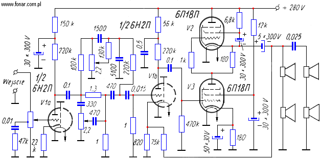
Fig. 2. Schematic diagram of an 2W amplifier without output transformer
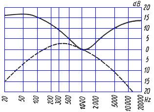
Fig. 3. Frequency characteristics of the amplifier from Fig. 2
The amplifier does not contain a separate phase inverter stage, and the signal voltage is applied only to the V3 tube. The voltage inducing the V2 tube arises on the resistor included in the cathode circuit of this tube. The resistivity of this resistor should be such as to ensure symmetrical operation of both tubes (in the given case 180). The amplifier has a negative feedback with a depth of 10dB supplied from the load to the cathode of the last-to-last stage of the amplifier. The low value of the internal resistance of the amplifier (90ohms) sufficiently suppresses the own vibrations of the loudspeakers. The output power of the amplifier is 2W with a harmonic content factor of 1.5%, which corresponds to the requirements for class I radio receivers. The amplifier sensitivity is 230mV and the average sound pressure is not less than 10μbar. The disadvantage of the amplifier without the phase inverting stage is the asymmetry of the voltage inducing the output tubes. The control grid of the V2 tube receives voltage with non-linear distortions carried by the V3 tube. As a result, the compensation of even harmonics, which is characteristic for counter-phase circuits, does not occur. In addition, this amplifier can work only in Class A. The amplifier uses two woofers type 2GD-6 and two tweeters type 1GD-17 with a total resistance of 960ohms at a frequency of 1000Hz.
Some difficulty in amplifiers without an output transformer is triggered by the supply of the second grid of the upper tube. To ensure correct operation of this tube, the screen grid should be connected to the cathode (for the variable component). Then, however, the resistor in the circuit of this grid is also connected in parallel to the load resistance and a portion of the output power is dissipated as a heat. Increasing the value of this resistor reduces the DC voltage on the screen grid, as a result of which the power output by the tube also decreases. As a compromise, a resistance of 6.8K was used. Instead of this resistor, a choke can be used, which will have high resistance to the AC signal component and a small resistivity to the DC current. This, however, complicates the design of the amplifier and is not the best solution in all cases.
Fig. 4 shows the diagram of the improved amplifier designed for higher-class radio and turntables. The pre-amplification stage with the V1 tube is common for both channels.
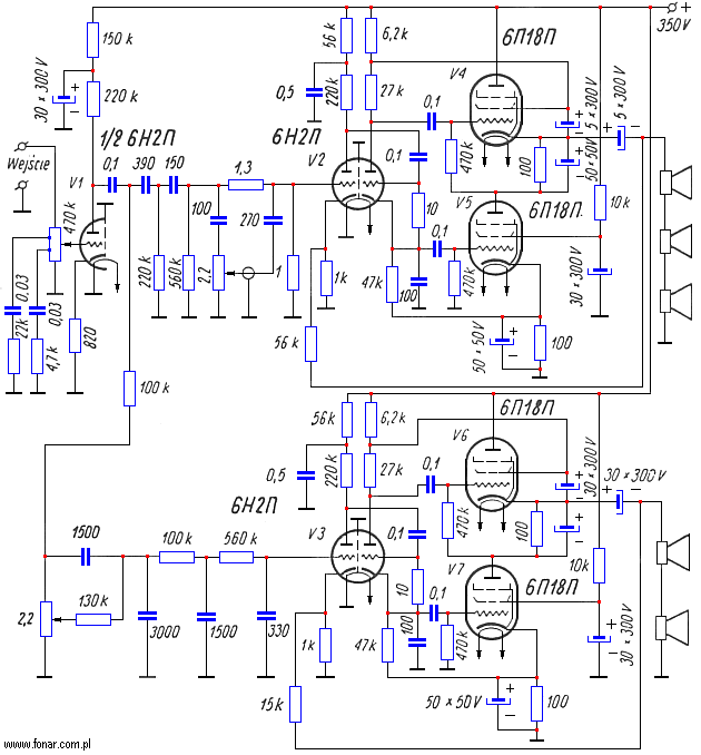
Fig. 4. Schematic diagram of the 6W amplifier
The channels are separated by means of a system of appropriate resistances and capacities in the tweeter channel and the subwoofer channel. The use of a phase inverter allowed a significant increase in the output power with small non-linear distortions. It should be emphasized that the input voltage for tubes V4 and V6 can not be taken from the entire anode resistance of the phase inverter, because then it would be applied not between the control grid and the cathode, and between the control grid and the output tube plate. In the amplifier in question, this voltage is obtained from resistors connected between the plate of the phase inverter stage tube and the screen grid of respective output tube.
The output power of each amplifier is 6W with a harmonic distortion of no more than 1% in the low frequency channel and - 2% in the high frequency channel. The amplifier's sensitivity is 0.2 V. Higher distortion in the tweeter is caused by a lower negative feedback, the depth of which is 21dB, when the low frequency range amplifier has a 28dB coupling depth. Internal resistance of the high-frequency amplifier is equal to 80ohms and low-frequency is 20ohms. The frequency response is shown in Fig. 5. The woofer consists of two 5GD-16 loudspeakers. The tweeter assembly consists of 3 WGD-2 loudspeakers.
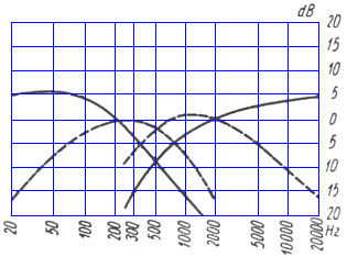
Fig. 5. Frequency characteristics of the amplifier from Fig. 4
The best amplifier in terms of quality indicators is shown in Fig. 6. The preamplifier was omitted here, which could be any system ensuring sufficiently small non-linear and frequency distortions.
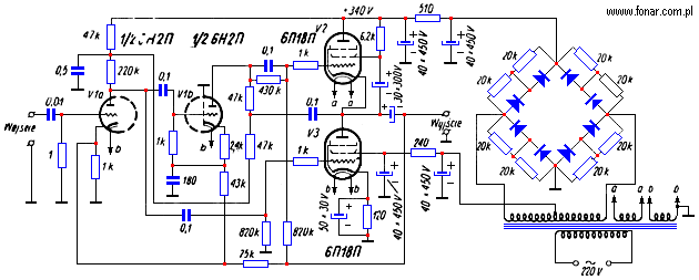
Fig. 6. Schematic diagram of the 7W amplifier
The amplifier uses a combination of feedback loops; it consists of a positive feedback circuit comprising the penultimate stage of the amplifier and a negative feedback circuit consisting of two stages. Such a coupling enables strong suppression of nonlinear distortions created in the amplifier. The positive feedback is obtained by supplying a part of the voltage from the cathode circuit of the V1b tube to the cathode circuit of the V1a tube. Negative feedback is obtained by supplying a part of the output voltage to the cathode of the V1a tube. The phase inverter anode has a galvanic connection with the V2 tube control grid. The negative voltage on this grid depends on the difference in voltage between the cathode of the tube and the divider formed of two resistors. Fig. 7 shows that the frequency response of the amplifier is flat from 20Hz to over 100kHz, which is a special feature of amplifiers without an output transformer.
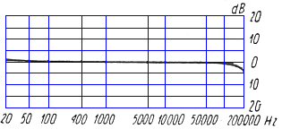
Fig. 7. Frequency characteristics of the amplifier from Fig.6
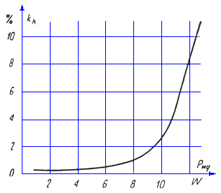
Fig.8. Harmonic distortion of the amplifier from Fig.6
The coefficient of harmonic distortion does not exceed 0.5% at 7W power (Fig.8). This ensures that the entire audio frequency band is reproduced practically without any distortion.
At the end it is worth mentioning that series-push-pull amplifiers can also work in AB and B class. For work similar to class B in the system shown in Fig. 6, instead of the automatic negative voltage for the V3 tube, a constant voltage source of 15V should be used. Such a change in the layout of the output power will increase by 10-20%.
It seems that amplifiers without output transformers (OTL amplifiers) have a large perspective of use in modern radio receivers, as well as in various amplifiers of electroacoustic systems intended for high-quality music reproduction. Systems without output transformers are particularly suitable for use in radio-amateur constructions because they enable the elimination of a labor-intensive and expensive output transformer.