M.R., "Negative feedback"
Radioamator 1954/04
The reason for the nonlinear distortions mentioned in the previous article is the non-linear relationship between the output voltage and the amplifier's input voltage, mainly caused by the non-linearity of the dynamic characteristics of the tubes working in the amplifier. Because at the current stage of development of radio technology we can not build a tube with ideally linear static characteristics, therefore the fight against non-linear distortions must follow a different path, namely to compensate for these distortions by means of special tube circuits.
One of the most effective ways to reduce of non-linear amplifier's distortion is the widespread use of negative feedback.
The feedback is a system by means of which a part of the energy from the amplifier's output circuit is transferred to the input circuit of the same amplifier.
The feedback can include all or one or two stages of amplifier. Depending on the phase that the reverse electrical waveforms have in relation to the waveforms supplied from the outside to the input circuit of the amplifier, the amplification of the system increases or decreases.
Negative feedback is a feedback that reduces the gain of the amplifier system. Due to the use of feedback, we lose always on amplification, but instead we gain on the quality of the amplifier. The gain loss can be easily compensated by adding one stage of reinforcement in the form of one additional tube.
To better understand the benefits of negative feedback, let us consider the following example.
We have amplifier with amplifying 10 times. A variable voltage source (eg a phono adapter) with an effective voltage U1 = 1V is connected to the input terminals. At the output of the amplifier we get a voltage 10 times greater, that is U2 = 10V (Fig.1).

Fig. 1
Let us assume that our amplifier with 10 volts at the output terminals has non-linear distortions (i.e., produces harmonic frequencies) in the amount of 10% (h = 10%). In addition, our amplifier produces an interfering voltage in the form of a mains hum because of incorrect filtering of the voltage rectified by the mains power supply. This voltage (let us denote it by Usz) is independent of the magnitude of the control voltage and equals, for example, 0.1V (i.e. Usz = 0.1V). When controlling the amplifier with 1V, ie at the output voltage U2 = 10V, the ratio of the interfering voltage to the voltage of the useful signal is equal to:
Suppose our amplifier is powered by a loudspeaker that needs only 5V to fully control it. There is therefore a need to reduce the output voltage by half, that is from 10 volts to 5 volts. We can do it in three different ways. Let's examine them one by one.
1. We reduce the voltage at the output of the amplifier using a suitable potentiometer P2 (as shown in Fig. 2) or a loudspeaker transformer with a 2:1 turn ratio.

Fig. 2
With this type of output voltage reduction, the amplifier remains fully actuated (10V at the output), and thus produces the same non-linear distortion as before (h = 10%). By reducing the output voltage halfway, we also reduce the interfering voltage in the same ratio. If the previous interfering voltage was 0.1V, it equals 0.05V. Although the interfering voltage decreased twice, the ratio of this voltage to the signal remained unchanged:

As we can see, this way of reducing the output voltage does not present any advantages.
2. However, we can reduce the output voltage of the amplifier from 10V to 5V by halving the input voltage of the amplifier instead of the output voltage, using the appropriate potentiometer P1 (Fig. 3).

Fig. 3
By reducing the input voltage, we reduce the degree of the amplifier's activation, and thus the non-linear distortion. Assuming that the content of harmonics is proportional to the input voltage, we get at five volts of the output voltage by half the ratio of harmonic content, i.e. h = 5%. We see that by reducing the voltage at the amplifier input we have received a lower distortion factor. But what about the interference?
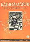
The interference voltage at the output terminals of the amplifier is, as we know, independent of the input voltage and is 0.1V. At the signal voltage at the output U2 = 5V, the ratio of interference to the signal is equal to:

so this ratio has deteriorated in relation to the previous one.
In the second alternative, we achieved a reduction in the distortion of the amplifier, but at the cost of increasing the hum of the power supply network. However, because the mains voltage can be removed in other ways, the second alternative is preferable to the first alternative.
3. However, we can use another method to reduce the output voltage, namely by means of negative feedback. For this purpose, let us enter one-tenth of the output voltage of the amplifier, ie Uz = 0.5V, to the amplifier's input and connect them in series with the voltage of the source U1 = 1V so that the resultant voltage on the input terminals of the amplifier is equal to the difference between the source voltage and the feedback voltage (Fig. 4)

Fig. 4
Us = U1- Uz = 1 - 0,5 = 0,5V
In this way we get the same reduction of the input voltage as in the second case, but without the use of a potentiometer. However, the layout from Fig. 4 has a number of new advantages in relation to the layout from Fig. 3, which we will consider in turn.
The influence of negative feedback on the noise reduction of the amplifier.
The internal noise of the amplifier is called all interfering voltages produced by the amplifier in the absence of the input signal. The internal noise of the amplifier also includes the hum of the power supply network appearing at the output terminals of the amplifier. Each amplifier can therefore be considered as a noise generator. Let us denote the voltage of noise produced inside the amplifier by Usz (Fig. 5).

Fig. 5
In our case, the noise voltage is Usz = 0.1V. The input voltage U'sz operates in series with the internal noise of Usz. It is k times reinforced by the amplifier and is -kU'sz. The coefficient k can be considered as amplifier amplification factor (in our example k = 10). Because the reverse voltage U'sz is applied with the reverse phase, the voltage -kU'sz has a negative sign. As a result, the noise voltage at the output of the amplifier is equal to:
(Usz - k.U'sz)
The feedback voltage U'sz is part of the resultant voltage at the output terminals, i.e:
 (1)
(1)
In our example:

The alpha factor, which is the ratio of the feedback voltage to the output voltage of the amplifier, is called the feedback coefficient. From the equation (1), we can calculate the U'sz feedback voltage. It is equal to:
 (2)
(2)
Substituting:

to the formula (2) we get the size of the reverse noise voltage U'sz:

After amplifying k times through the amplifier, we get 10.0,005 = 0.05V.
The resultant noise voltage at the output terminals of the amplifier is equal to:
U = Usz - k.U'sz = 0,1 - 0,05 = 0,05 V
In relation to the signal, which is equal to 5V, the noise voltage is one hundredth, i.e. the ratio of noise to the signal has been improved compared to the second alternative.
In the general case, the noise voltage after applying the feedback will be:
 (3)
(3)
We see that by using negative feedback the internal noise of the amplifier decreased by the value of:
 (4)
(4)
The number ß can be called the degree of feedback. It tells us in what proportion the gain of the amplifier has decreased. In our example:

The influence of negative feedback on the harmonic content of the amplifier
As in the case of noise, we can also consider the amplifier to be a harmonic frequency generator. Using the same reasoning as previously it is easy to show that by supplying the amplifier with some of the harmonic voltages from the output terminals of the amplifier, but in the reverse phase, we obtain a reduction in the harmonic content factor at the output of the amplifier in the k ratio:
 (5)
(5)
Because we assumed that at 5 volts of the output voltage the amplifier's harmonic content factor was 5%, therefore, after applying negative feedback, this coefficient will decrease twice, ie it will amount to:
h' = 2,5%
We see that the reduction of the output voltage of the amplifier by the negative feedback method combines the advantages of the circuits of Fig. 1 and Fig. 2, however, without their disadvantages. In relation to non-linear distortions, this system is better than the one shown in Fig.2.
The influence of negative feedback on the stabilization of the amplifier's operation
The degree of feedback defined by the formula:
(6)
gives an idea of the amplifier gain reduction caused by the negative feedback.
If by k we mean amplifier amplification factor without the use of feedback, then after applying the feedback the new amplification factor of the system will be k ', whereby:
 (7)
(7)
In our example (Fig. 4) we have k = 10, alpha = 0.1. Therefore the amplification factor of the feedback system is equal to:

The input voltage U1 = 1V is amplified to voltage:
U2 = k'.U1 = 5.1 = 5V
By increasing the alpha factor, i.e. by increasing the amount of the feedback voltage Uz, we can decrease the gain of the system k 'according to the formula (7). One can ask, to what extent can the amplification of the system be reduced by means of negative feedback? The maximum value of the feedback voltage Uz can be equal in the extreme case of the output voltage U2. Then we have alpha = 1. substituting alpha = 1 for the formula (7) we get:

Since k is usually much larger than one, the limit value of the amplification coefficient of the feedback system is approximately equal to one. In other words, by using negative feedback, reduce the gain of the amplifier to the value of k '= 1. This will happen when alpha = 1, that is, when the entire output voltage of the system will be led in the reverse phase to the input of the amplifier. The amplifier stops then amplifying. Of course, in practice, such a strong feedback loop is not used, because it would be a total abandonment of the reinforcing properties of the system.
Usually, by means of negative feedback, the gain of the amplifier is reduced by at most 10-20 times, which is sufficient to significantly improve the quality of the amplifier, reducing the distortion and noise of the amplifier in the same ratio.
Equation (7) can be written in another form. We will divide the numerator and denominator of the right side of the equation by k:
 (8)
(8)
If the gain factor of the amplifier is very large, e.g. k = 1000, then the formula (8) can be reduced to the form:
 (9)
(9)
The last formula shows that the amplification of the feedback system does not depend on the amplifier amplification factor k, but only on the negative feedback coefficient alpha. For example, if we want to obtain the gain factor k '= 100, we must apply

that is, one hundredth part of the output voltage must lead to the input of the amplifier.
From the formula (9) one more important conclusion arises, namely that the obtained gain of the feedback system is practically independent of the amplifier amplifier k factor, if of course:

Over time, and even during the amplifier's work, the coefficient k can change, but it will not affect the amplification of the feedback system, because the amplification of this system, i.e. k, does not depend on it.
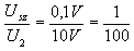
It is best to visualize the above property of the system with feedback on the example. For example, we have an amplifier with a gain of k = 2,000. We use negative feedback by taking:
According to formula (7) we will obtain a resultant system gain equal to:
If, for example, due to the aging of the tubes, the gain factor of the amplifier decreases from 2000 to 1500, the amplification of the system k 'will change only slightly. For k = 1500 we will get from formula (7):

Thus, we can see that the amplification change of the amplifier itself does not affect the amplification of the feedback circuit. The amplifier after the use of feedback has become stable, i.e. not very sensitive to changes in tube parameters, which only affect the amplification coefficient k, but have little effect on the amplification of the whole system.
The gain factor k of the amplifier may not only change due to the aging of the tubes, but this coefficient generally has different values depending on the frequency of the amplified waveforms. Amplification of the amplifier usually decreases at the ends of the transmitted frequency band, i.e. at low and high tones. In other words, the amplifier does not have a straight frequency characteristic over the entire acoustic range. These unevenness of gain at different frequencies are compensated by the use of negative feedback. Negative feedback not only reduces non-linear distortions, but also, as a result, linear distortions.
Finally, we should also mention the effect of negative feedback on the internal resistance of the amplifier.
With a normal amplifier, the output voltage of the amplifier depends to a large extent on the load resistance of the amplifier. The use of strong voltage feedback greatly mitigates the above fluctuations in the output voltage. One can visualize the operation of negative feedback in the following way. Let us assume that the load resistance of the amplifier decreased, as a result of which the voltage on the amplifier terminals also decreased. This also entails a decrease in the feedback voltage Uz which is equal to alpha.U2. The reduction of the voltage Uz causes an increase of the control voltage, and thus an increase of the output voltage of the amplifier. Negative feedback tries to keep the output voltage at the previous level regardless of the load resistance of the amplifier.
The electrical waveforms in the output circuit therefore occur in such a way as if the amplifier had very low internal resistance.
This detail is important for amplifiers that work on variable loads, e.g., radio-frequency amplifiers, to which a different number of loudspeakers are connected. Negative feedback automatically keeps the output voltage constant, regardless of the number of speakers attached.