M.R., "Tube in the amplifier output stage"
Radioamator 1953/08
The biggest problem for the designer who builds himself a tube amplifier is to properly match the resistance of his speaker to the output tube that works as a loudspeaker tube. This conclusion results from the content of letters coming to the Radioamator's office, in which the most common questions are of this type: I have a tube eg P.X.25 (usually it is a type of obsolete tube). I am going to use it as a speaker tube. How do I get the acoustic power from it and how to select the output transformer to match the dynamic loudspeaker with a 5ohm resistance coil? Or another question. Is a 40: 1 transformer ratio suitable for a CL4 tube? etc. These and similar questions can be generally answered by introducing the readers to the elementary theory of the tube, working at the power stage.
The task that the output lamp has to meet in the radio is different than the task of tubes working in previous stages. We discussed the work of the tube in amplification systems, in which the most important task of the tube was to achieve the greatest possible voltage gain. The tube's power was irrelevant. However, the issue is different in the case of the output tube. Here, vice versa, the degree of amplification of the voltage output system is irrelevant, but the first issue is the power of the tube, and in particular the usable (acoustic) power that we can receive with the loudspeaker attached to the tube when the tube is fully activated.
Tube's power
Speaking of tube power, we have to distinguish two powers with regard to the tube, namely the tube's plate dissipation and the tube's useful power. What is the tube's plate dissipation or in other words the power of the tube?
We know that in the steady state, i.e. when the tube is not controlled by variable grid voltage, a direct current flows through the tube. This constant component of the anode current depends on the grid bias and the anode voltage. The anode current flowing through the tube is supplied by the anode battery or the power rectifier. If we denote the anode current flowing through the tube as Iao, and the anode constant voltage as Uao, then the product Uao.Iao is the power that the tube draws from the anode source. This power completely turns into heat in the tube. Under the influence of this heat, the anode of the tube warms up. The heat lost in the tube can not exceed a certain value for a given type of tube, if you do not want to damage the tube. This maximum power, which the tube anode can, without damage convert into heat, is called the admissive power or maximum plate dissipation. It is cataloged for each type of tube. For example, for the AL4 tube the admission power is 9 watts, for the EL5 tube - 18 watts, etc. Regarding the tube's plate dissipation, we can talk about a 9-watt, 18-watt, 2-watt tube, etc. This does not mean, however, that the power usable from these tubes is equal to 9 watts, 18 watts or 2 watts respectively. The usable power delivered during the tube operation to the loudspeaker is somewhat dependent on the allowable plate dissipation, but it also depends on other factors that will still be mentioned. Knowing the tube's admissive power from the catalog, we can always determine the maximum anode constant current for a given anode voltage Uao, which in the steady state can flow through the tube without damaging the tube. The value of this current is calculated depending on:
Uao.Iao = Pad (1)
if by means of Pad, we mark the maximum allowable dissipation power of the tube. From this equality it follows that:
 (2)
(2)
The anode current Iao is set using a negative grid bias. The correct adjustment of the anode current through the negative voltage of the tube grid is the first basic condition for the good use of the loudspeaker tube. However, care should be taken not to exceed the anode current determined according to formula (2), as this may damage the tube. Overheating of the tube plate causes, in most cases, a deterioration of the vacuum of the tube due to the fact that the heated plate of the tube ejects residual occluded gases.
The second condition for good use of the tube in the power system is the use of the anode voltage, which is the maximum for a given type of tube. This voltage is also given in tube catalogs. For example, for the AL4 speaker tube, we read in the tube catalog: Uao = 250V, Iao = 36mA, Us = -6V, Pad = 9W. We are convinced that thel 36mA anode current using the 250V anode voltage is the maximum permissible current resulting from the macimum dissipation power of the Pad = 9W tube. We have according to the formula (1) 250.36.10-3 = 9W. If we applied a lower anode voltage, eg Uao = 200V, then we could, without tube damage, increase the anode current to the value of:
Conversely, if we applied anode voltage higher than 250V, e.g. Uao = 300V, then we would have to reduce the anode current (by setting the negative grid voltage) to the value of:
In order not to calculate the maximum anode current for any anode voltage each time - we can depend on the anode voltage expressed by the formula (2) graphically on the anode characteristics chart of the tube. We will get a curve, which is called hyperbola. Because every point lying on this hyperbola corresponds to the maximum dssipation power of a given tube, we call this hyperbolic curve of the tube's maximum power. Hyperbola of the maximum power Pad = 9W for the AL4 tube is shown in a dashed line in Fig.1.
Fig.1
We can see that this hyperbola passes through the points we previously calculated with the account, namely: (Ua = 300V, Ia = 30mA), (Ua = 200V, Ia = 45mA). The initial working point of the loudspeaker tube should be chosen so that it lies on the hyperbola of the admissive power, or below this hyperbola, but in no case above this curve. Hyperbola of admissive power intersects the tube characteristics corresponding to different grid negative voltages. By searching for the characteristics going through a pre-selected starting point of work, lying on the hyperbola of power, we can determine the necessary negative grid bias determining the desired anode current. For example, through the Po point corresponding to the anode voltage Ua = 250V and the current Ia = 36mA, the tube characteristics pass, which belongs to the negative voltage Us = -6V. It follows that to set the 36mA current, negative grid voltage -6V is needed. This negative grid voltage can be obtained automatically, including a cathode resistance between the cathode and the ground, such that the 36mA anode current causes a voltage drop of 6V on it. From Ohm's law the value of this cathode resistance is equal to:
In this way, we have determined the initial working point of the loudspeaker tube which is most suitable due to the highest possible usable (acoustic) power.
The useful power of the tube
The useful power is the power that the tube dissipates on anode resistance. In the output stage, a transformer is usually included in the anode circuit of the tube, which transfers electrical power from the anode circuit of the tube to the loudspeaker. For the anode current DC component, the primary resistance of the transformer winding is insignificantly small, and as a result it can be omitted in analysis of useful power. Only during the operation of the tube, when there are fluctuations in the anode current caused by variable grid voltage, AC voltages are created at the terminals of the primary winding of the speaker transformer, which are transferred to the loudspeaker through the secondary winding of the transformer and cause the movement of the moving speaker coil. The power of alternating currents caused by the variable voltage applied to the grid of the output tube is transferred by the transformer. This power is just the tube's useful power. The useful power of the tube is to a certain extent dependent on the tube's maximum plate dissipation, but it also depends on the type of tube. From a loudspeaker pentode, you can generally get more useful power than with a triode with the same admissive power. The tube in the steady state, although the anode current flows through it, does not emit power to the loudspeaker. Only when the tube is controlled by variable voltage, the useful power increases. Interesting is the issue of what is the maximum usable power that we can get from a given tube and what it depends on, or a different question: what conditions must be met in order to obtain the maximum possible useful power from a given tube? We will try to answer this question.
Output stage system with ideal transformer
A typical system of the stage stage with a triode is shown in Fig.2.
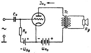
Fig. 2
The transformer Tr with the appropriate turn ratio is used to adjust the resistance of the loudspeaker coil to the tube to achieve the maximum sound power. The conclusion is that the correct operation of the system will depend primarily on the well-chosen transformer ratio and its correct performance. Let's think about what properties an ideal transformer should have.
The purpose and task of the transformer is to transmit the power of alternating currents from the anode circuit of the tube to the loudspeaker circuit. With an ideal transformer, the transmission of electric power takes place without loss, that is, the transformer itself does not absorb any power as an electric power conveyor. It follows that the Ohm resistance of the ideal transformer windings should be equal to zero, so the winding wire of the transformer should have a correspondingly large cross-section. We will see later to what extent this approximation to the ideal is practically possible. Further, in the iron core of the ideal transformer, there can be no loss of power, due to magnetic hysteresis or as a result of eddy currents. In practice, this condition is also not 100% available.
Let us now ask what the inductance of the ideal transformer should be on the primary side. The answer to this question stems from the reasoning behind the transformer idle run. The unloaded transformer on the secondary side, connected to the AC power source should not take any current from the source, i.e. that its apparent resistance between the primary terminals should be infinitely large, so the primary inductance of the ideal transformer should also be infinitely large. On the other hand, when the secondary terminals are shorted, there should also be a short-circuit of the source of alternating currents to which the transformer is connected, ie the apparent resistance of the compact transformer - between the primary terminals should be equal to zero. In this way, the transformer is perfect in two extreme cases. During normal operation, the transformer is loaded on the secondary side with the resistance of the loudspeaker coil, which can be taken as real resistance. Under the influence of the voltage, which occurs on the secondary terminals, a current flows through this resistance, which in turn induces a current in the primary winding of the transformer. Of course, the current drawn by the transformer from the source must be so large that the power absorbed by the transformer from the source is equal to the power allocated on the transformer load resistance on the secondary side. Because the electric power is equal to the product of voltage by the current, the product of the primary voltage by the primary current must be equal to the product of the secondary voltage by the secondary current:
U1.I1 = U2.I2 (3)
Fig. 3 shows the transformer connected to the AC power source and loaded with resistance R2 and its substitute circuit; n1 and n2 are the number of windings of the primary and secondary windings. Resistance R1 is the transformer substitute resistance that is seen by the source between the primary terminals of the transformer.
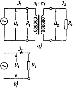
Fig. 3
Let's calculate this substitute resistance. For this purpose, let's substitute in the equation (3) instead of I2 the value of this current, which results from Ohm's law:

and instead of I1, let's substitute:

After substitution we will get equality :
 (4)
(4)
From the last equality, we calculate R1:
 (5)
(5)
The voltage ratio at the transformer terminals is called the voltage ratio of the transformer and is marked by p. As it results from the transformer theory, the transformer voltage ratio is equal to the ratio of the number of winding windings, i.e.

Substituting the last equality to (5) we get:
 (6)
(6)
Knowing the load resistance R2 and knowing the transformer p, we can always calculate according to the formula (6) the resistance R1 transferred to the primary side. By changing the ratio of the transformer p we can also change the resistance transferred R1. Conversely, knowing how big the R1 transfer resistance is to be, we can always choose the transformer ratio so that the resistance of the R2 (loudspeaker) is seen on the primary side of the transformer as a resistance equal to R1, namely:
 (7)
(7)
For example: the speaker coil has a resistance of R2 = 5ohm. We want to increase this resistance on the primary side of the transformer to the value of R1 = 7000om. What turn ratio must a transformer have? From the formula (7) we calculate:
so the transformer must have turn ratio 37.5:1.
Now the next question is how to determine the R1 resistance for a given loudspeaker tube? From the well-chosen value of this resistance depends the maximum useful power that we can achieve from a given tube. Resistance R1 is the resistance of the tube through which alternating currents flow, causing a voltage drop on it. The amplitude of these anode currents can not exceed the value of the component of the anode constant Iao, otherwise the AC current amplitude will be cut off and serious distortions will occur. For the AL4 tube, anode current fluctuations should not exceed 36mA. Therefore, the highest amplitude of the AC anode current for this tube should not exceed the value of Ia = 36mA. This current, flowing through the resistance Ra = R1, causes a voltage drop Ua = Ia.R1. The value of this voltage is higher or lower, depending on the resistance value R1. If the resistance R1 is small, then also the voltage amplitudes on this resistance caused by the current amplitudes Ia = 36mA, will be small and the power dissipated on the resistance R1 is also small. As the resistance R1 increases, the voltage amplitudes Ua = Ia.R1 increase and at the same time the useful power increases. Moreover, it is not possible to let amplitudes of anode voltage fluctuations be greater than the DC component of anode voltage, i.e. in our case, higher than 250V, because in this case the peak of voltage amplitudes would be cut off. Thus, we see that the most favorable will be the anode resistance, on which the maximum current fluctuations Ia = Iao will cause maximum voltage fluctuations or equal to Ua = Uao. The optimal anode resistance will therefore be equal, according to Ohm's law:
 (8)
(8)
For the AL4 tube we get substituting Iao = 36mA, Uao = 250V:
Thus, we can see that the optimal resistance of the pentode depends only on the operating conditions of the tube, i.e. on the applied voltage supplying the tube and on the chosen Io anode current, it does not depend on the parameters of the itself itself. Of course, the above reasoning is approximate, but gives numerical results sufficiently accurate. Mostly, we can donate calculations of optimal anode resistance Ra, because in tube catalogs this resistance is usually given. For the AL4 speaker pentode, we find in the catalog the value of Ra = 7000, which is the same value we previously calculated. Knowing the optimal resistance of Ra and the resistance of the loudspeaker coil, we can calculate the necessary transformer ratio:
This turn ratio, as we already know, is 37.5:1.
Calculation of the optimal resistance according to (8) is only valid for the pentode, but does not apply to the loudspeaker triodes. For the triode, the optimal resistance of the work is almost twice smaller than the resistance that falls to us from calculations according to the formula (8).
Maximum useful power
When calculating the optimal working resistance of the pentode, we assumed that the anodie current is 36mA, equal to the anode DC component, simultaneously causes the optimum voltage variation with an amplitude of 250V, i.e. an amplitude equal to the Uao constant voltage component. With this assumption the useful power obtained from the tube would be equal to:
 (9)
(9)
The AC power is calculated as the product of the effective AC voltage by the effective AC current. On the other hand, we know that the effective value of voltage or alternating current equals the amplitude of the variable divided by the square root of 2. This results in formula (9).
Ideally, you could get a usable power equal to half the admission power with a pentode. For example, from an AL4 speaker pentode with a 9W admissive power - theoretically, the maximum usable power would be 4.5W. In reality, however, this power can not be achieved. Fig. 4 shows a graph of the working characteristic corresponding to the optimal resistance of 7000om. It is a straight line passing through the initial work point Po and at such a slope that it connects points 72mA on the Ia axis and 500V on the Ua axis.
Fig. 4
During the maximum control of the tube, the grid voltage changes from -6V to zero and in the second direction to -12V. Voltages with a greater amplitude than 6V would cause overdriving of the tube and high distortion. The working point with this tube moves from Po to A and from A to B. The anode current at point A has a value of approximately 70mA, while at point B approximately 10mA. The double amplitude of the current variations is therefore 70 - 10 = 60mA. The average amplitude of fluctuations in the anode current is equal to:
Similarly, we will determine the average amplitude of anode voltage fluctuations. At point A, the anode voltage is around 20V, in point B about 420V. The double amplitude of voltage variations is therefore 420 - 20 = 400V. Hence the average amplitude of alternating voltage:
Having determined the current and AC voltage amplitudes, we can calculate the maximum useful power obtained from the AL4 tube:
It is much less than before we calculated for the ideal case, with which we assumed that the amplitude of the anode current Ia is equal to 36mA, and the voltage amplitude Ua is equal to 250V. In fact, if we do not want to get too distorted waveforms in the speaker, these amplitudes are slightly smaller, which implies a reduction in the usable power of the tube.
We can practically remember that from the speaker pentode we can obtain the maximum useful power equal to 33% to 40% of the maximum anode dissipation of the tube, provided that the loudspeaker is perfectly matched to the tube, with optimal working resistance:

As we can see, the issue of adjusting the loudspeaker's resistance to the tube and determining the maximum power that we can get from the pentode under these conditions is not difficult.
Next time we will see how the same problem is presented at the loudspeaker triode. It can already be said that in the case of triode due to the different shape of anode characteristics, this problem is presented less favorably than at the pentode. That is why the loudspeaker pentode has become more popular output than the triode.
")
")
")
")
")