NOVEMBER - DECEMBER 1947 NO. 11/12 (Polish Radio Publishing Office, price PLN 60)
CONTENT OF THE NUMBER (in short):
- From home and abroad.
- Television in aviation.
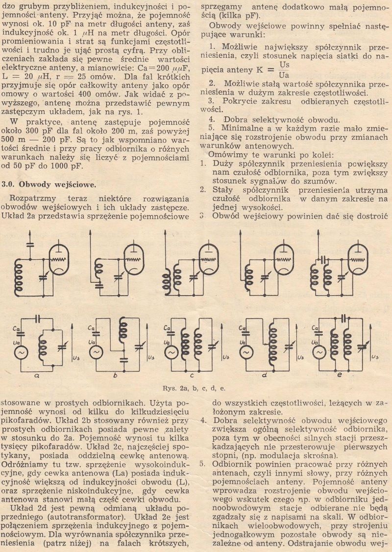
- Principles of calculating receivers and amplifiers (continued).
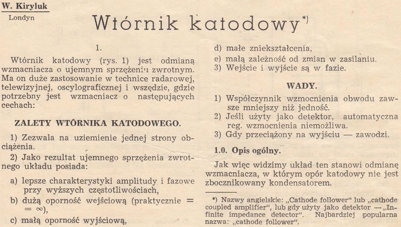
- Cathode follower.
- Schematic overview.
- Cheap dual-circuit radio for beginners.
- Ham radio corner.
- Nomogram No. 17.
CONTENTS OF THE NUMBER (detailed))
FROM THE COUNTRY AND ABROAD (1)
- THE SOCIAL NATIONAL RADIOPHONIZATION COMMITTEE ORGANIZES AN CAMPAIGN ACTION FOR AMATEURS RADIO.
The broadcasting of the country, undertaken just after the war and still conducted, mainly involved investments, i.e. the construction of radio broadcasting equipment and the assembly of a new one on our ground - wired radio, based on a network of radio stations and collective radio devices. The aforementioned devices have become an indispensable base for the further development of the reborn radio broadcasting.
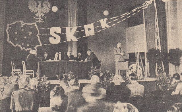
The Chief Executive of Polish Radio, Wilhelm Billig, speaks during the General Social Congress of the National Broadcasting Committee.
- INTERNATIONAL RADIO EXHIBITION IN PRAGUE.
At the 1st International Radio Exhibition in Prague, organized on the occasion of the 25th anniversary of the Czechoslovak Radio, we saw, next to the impressive exhibits of the Czechoslovakian pavilion, the Hungarian and Polish radio pavilions.
The Polish pavilion enjoyed a special attendance, drawing visitors' attention to both the aesthetics of the exhibits and their content, illustrating the impressive achievements of our radio broadcasting.
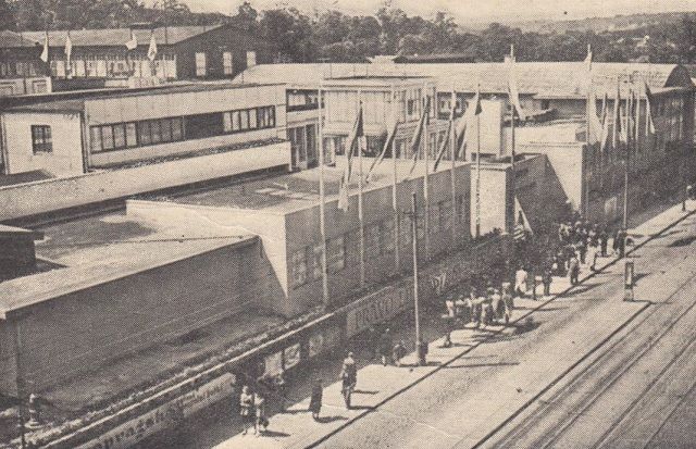
General view of the Exhibition.
Television in aviation (4)
The rapid development of television technology over the past few years has led to its application in a wide variety of fields. One of the areas where television has gained a prominent place is military aviation. In the last war, with the help of television devices, large-caliber bombs were aimed at the target from a distance, intelligence planes transmitted images from the battlefield to the headquarters, etc. The idea of using television in aviation arose back in 1934, when the famous television pioneer Dr. VK Zworykin proposed the use of television devices to successfully target bombs; at that time, suicide squads of human torpedoes were organized in Japan.
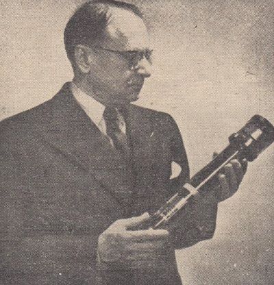
dr. V. K. Zworykin (inventor of the Iconoscope)
The first model of the device was developed by R.C.A. in 1935. In the years 1941 and 1942, the weight of the devices was improved and reduced to several dozen kilograms, and the various difficulties associated with the operation of the device in a large range of temperatures, humidity and altitudes were overcome. Basically three types have been developed: BLOCK I, II and III) used primarily for directing slide bombs and for close intelligence operations, MIMO counterpart of the previous type for bombs thrown directly at the target and RING - a normal 1kW TV station with two or three cameras intended for for intelligence purposes.
The "block" device was a TV transmitter assembled in a GB-4 2000-pound bomb. A bomb dropped from an airplane about 20 km from the target was gliding; the TV camera attached at the bottom transmitted the image "seen" by the bomb using a transmitter (15 W power in a 300 Mc / s belt) and a directional antenna.
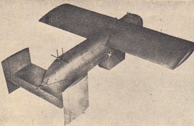
Bomba GB-4.
In the mother plane, which could circulate up to 25 km from the target, the image was observed by a bombardier, which, with two miniature manipulators, controlled the bomb's rudder by radio and thus aimed it at the target. Devices of this kind were built into flying fortresses.
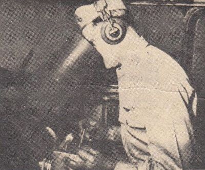
Bombardier controlling the GB-4 bomb.
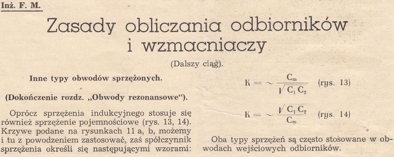
Principles of calculating receivers and amplifiers (continued) (7)
Other types of coupled circuits.
(Completion of the chapter "Resonant circuits)"
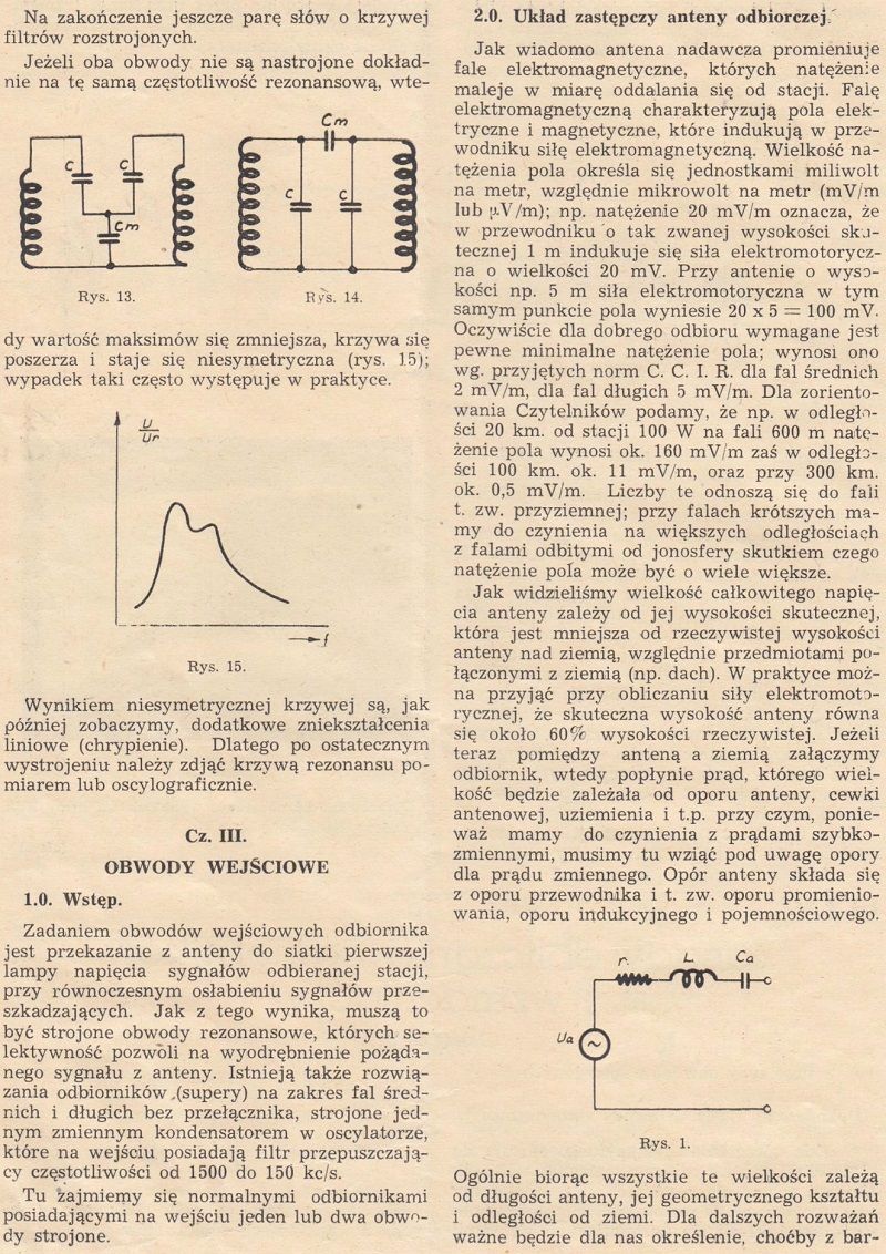
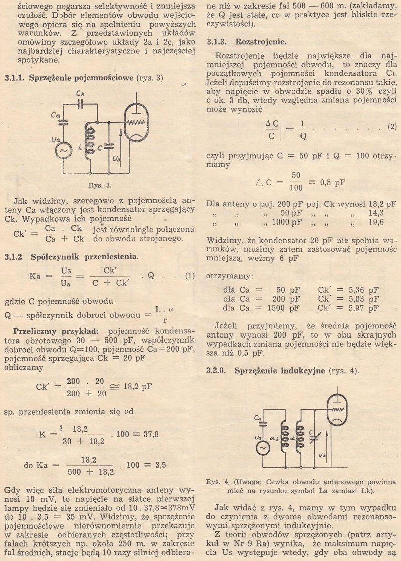
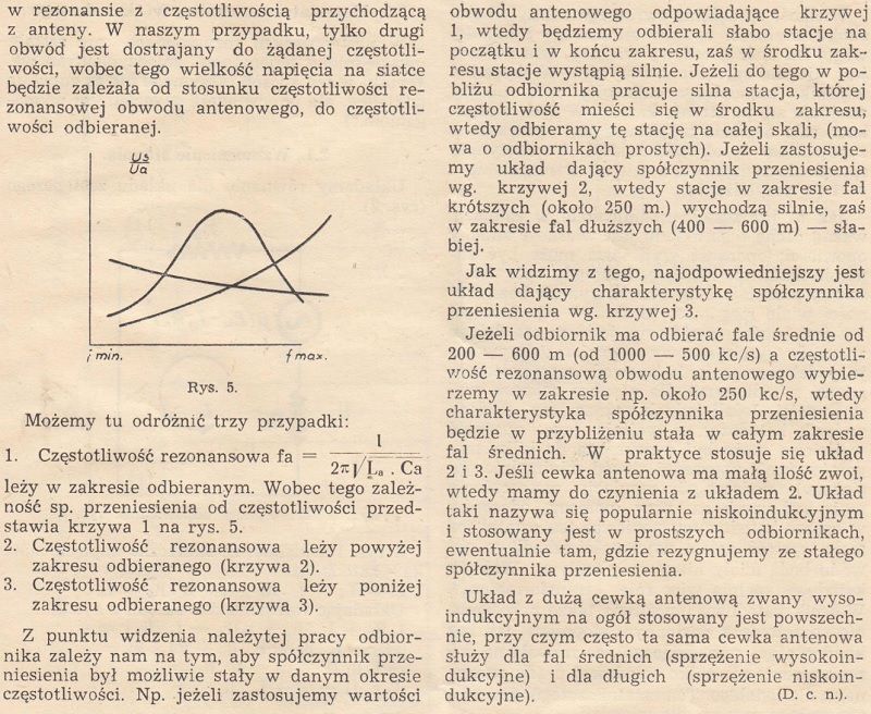
In addition to inductive coupling, also a capacitive coupling is used (Fig. 13, 14). The curves given in Figures 11a and 11b can also be successfully applied here, and the coupling coefficient is defined by the following formulas: ...
Cathode follower (11)
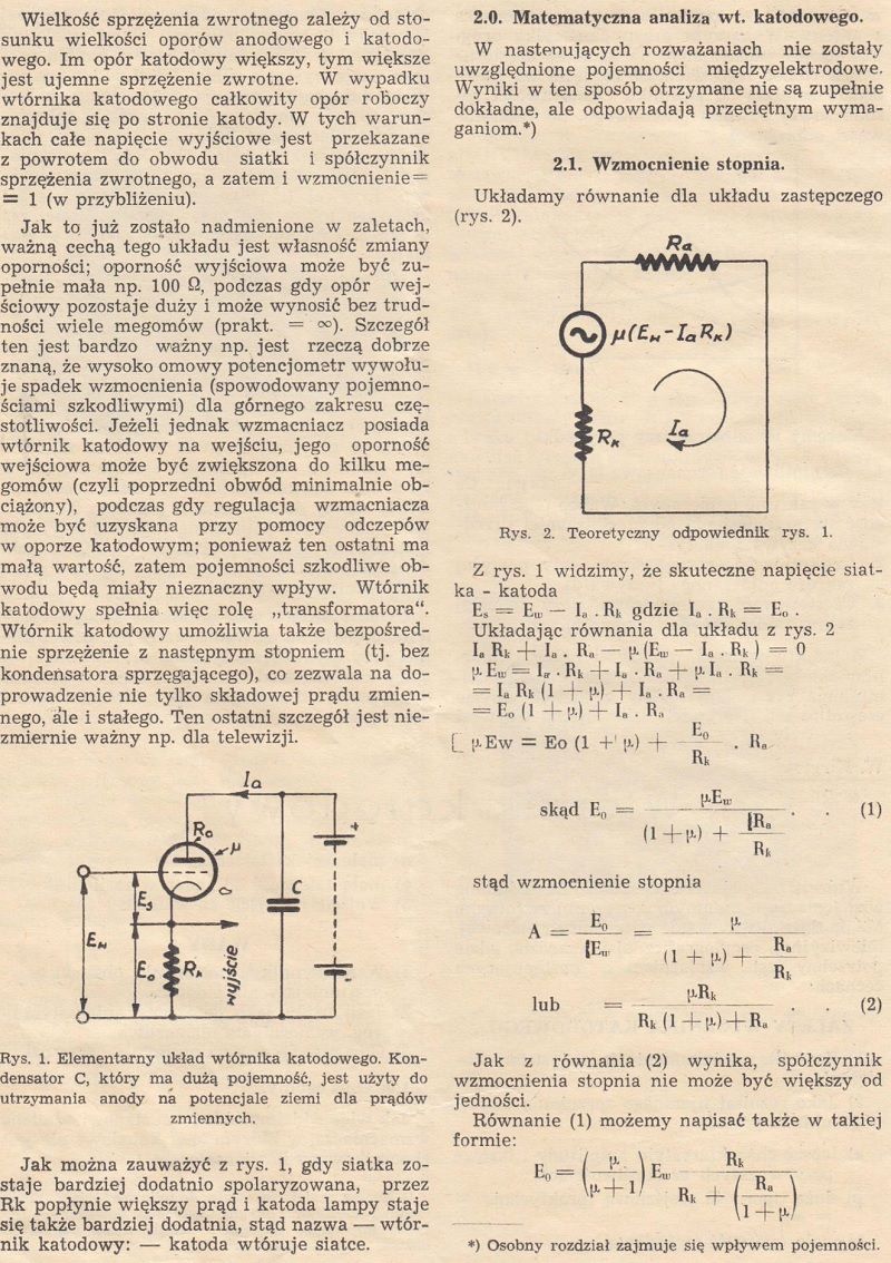
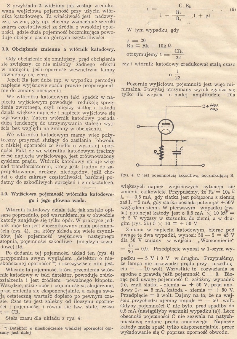
The cathode follower (Fig. 1) is a type of amplifier with negative feedback. It is widely used in radar, television, oscillography technology and wherever an amplifier with the following features is needed:...


Schematic overview (17)
Diagram No. 38 shows the GRAETZ 66W 370642 / A receiver circuit.
It is a six-circuit superheterodyne, three-tubes (plus a fourth rectifier), with three normal wavebands (short, medium and long).
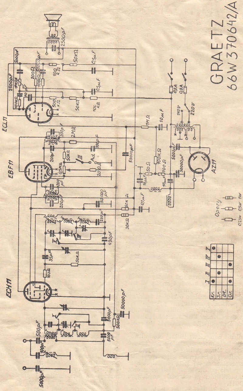
Schematic diagram No 38.
Scheme No. 39 shows the electronic system of the RSZ-47 (AGA - 1743) receiver, made by P.Z.T.R.
It is a six-circuit superheterodyne, working on US-made 7-volt electron tubes, three-band, with an intermediate frequency of 463 kc / s.

Schematic diagram No 39.
Low-cost dual circuit receiver for beginners (20)
A young radio amateur, after experiments on single-circuit boxes, usually wants to expand his receiver in order to increase both the range of the receiver and the selectivity, which in a single-circuit receiver presents a lot to be desired.
Below is a description of a low-cost receiver that is simple to build but produces encouraging results.
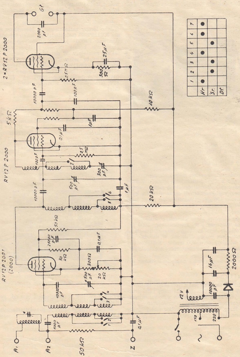
Schematic diagram of the receiver.
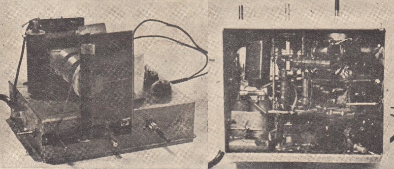
View of the assembled system.
Amateur Radio Corner - Transmitters Part I (23)
How oscillations arise in the transmitter.
Before we proceed to the descriptions of the construction and operation of transmitters, we will familiarize beginners with short wave carriers with the essence of electromagnetic vibrations in resonant circuits, in circuits that are an essential element of every transmitter.
For a better understanding of phenomena, we will first discuss similar patterns that we encounter in everyday life. Consider, for example, a pendulum clock; provided it is wound, the pendulum moves steadily, and the energy to cover friction losses is supplied by the tensioned spring via levers, gears, etc.

Fig. 1.
Consider a separate pendulum as in fig. 1 in the form of a weight suspended on a string...
Our readers write (27)
I have built a superheterodyne, the final diagram of which, after numerous modifications to the device, is attached.
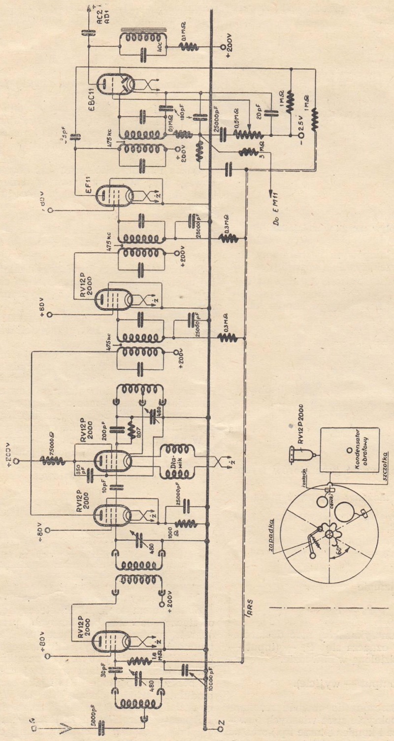
Fig. 1. Schematic diagram of superheterodyne.
Editor's Responses (30)
- "Majster Popsuj", Warsaw.
By applying earth ground directly to the control grid of the radio tube directly from the power network, such a large emission current flowed through it that it burned its filament in a very short time. Manipulating with universal type receivers requires great care and attention.
From new books (30)
The Polish Radio Publishing Office has published a book entitled "Physical basics of radio engineering", the English author M. Nelkon, an experienced educator in training radio technicians.
Nomogram No. 17 - Weakening of low frequencies in the resistive amplifier (31)


RADIO Monthly magazine for Technicians and Amateurs Year II - 1947 - Table of Contents (cover page 3)
