
Radio engineering time travel (1929)
I invite you to look at the "pictures" related to radio technology in 1929. They come from various sources. The gallery has its sister version in Polish and Russian. Versions in other languages will be added successively. More detailed descriptions can be found in other language versions (articles are related and can be displayed by clicking on the icons with flags on the left, top of the TRIODA website). Of course, I will complement translations of signatures quite slowly. All descriptions are displayed using the present tense and not the past - this is not a mistake only deliberate action - a reference to the original descriptions from those years. In order not to delay the possibility of viewing the gallery, this site is made available as a "site under construction" - for which I apologize to all guests. At the beginning and end of each set of photographs there are links allowing to change the period - calendar year.
[Previous period] [Next period]
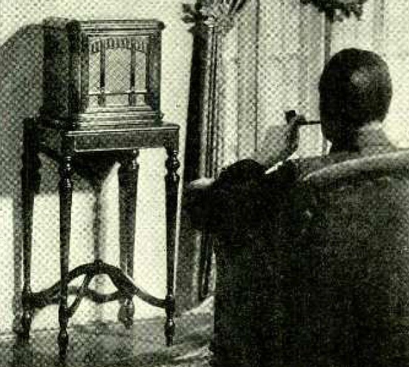
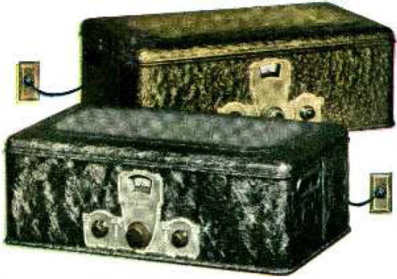
The Jensen Model 7 Cabinet.
Advertisement
"This beautifully designed cabinet harmoniously fits into artistically furnished music and drawing rooms. Jensen Dynamic Speakers are made in types to operate with 110 volt A. C. house current, 6 volt storage battery,"A" eliminator or trickle charger, 110 volt D. C. house current and 90 to 180 volt D. C. current as provided by many of the late model radio sets. The sensitivity of the instruments is the same in any case..."
(Radio for January, 1929)
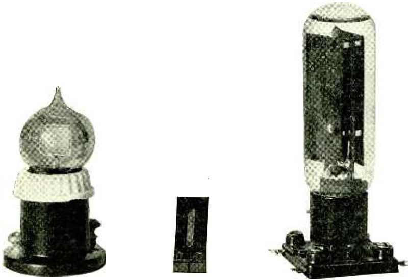
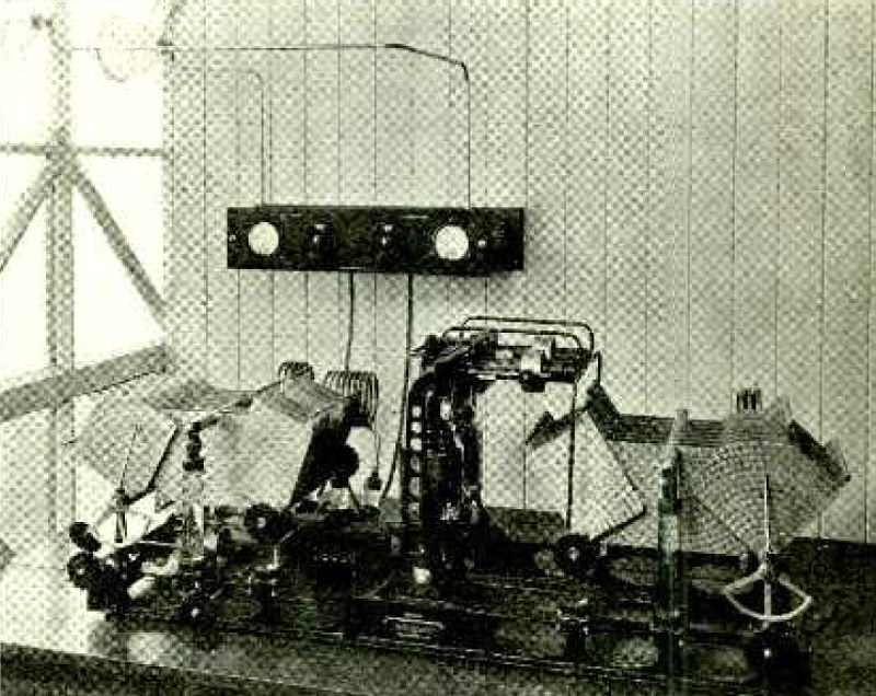
Types of Light Sensitive Devices; on left, Potassium -Hydride Cell; in center, Selenium Cell; on right, Copper -Oxide Cell.
Article: Radio Picture Transmission and Reception. Photoelectric Equipment and Methods for Visual Communication.
"The transmission of information over great distances in short intervals of time is effected solely by electrical means. When we communicate directly with another person, we ordinarily do so by an appeal to the senses of sight or hearing; that is, we either show or tell our vis -a -vis something. But when we are beyond the physical range of these senses, we must employ electrical communication channels..."
(Radio for January, 1929)
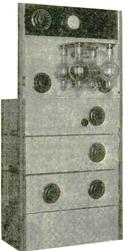
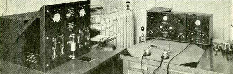
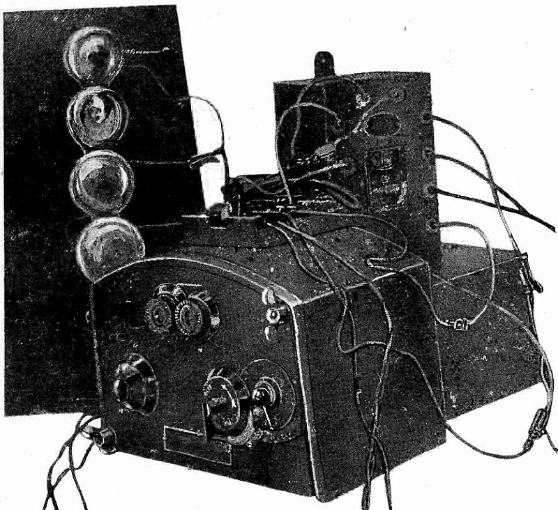
Complete Crystal- Controlled Transmitter.
Article: Construction of Crystal- Controlled Transmitter.
"Crystal control has peculiar advantages in a radiotelephone transmitter, over and above those accruing from frequency stabilization. Ordinary crystal- control oscillators seldom run higher than 5 or 10 watts in power, and amplification is used to bring the r.f. energy up to the desired level. It is possible, then, to modulate at low power, with a minimum of equipment, on one of the initial r.f. stages. This is contrasted with the usual transmitter system employing Heising modulation, where the number of tubes required for modulation is at least equal to, and for best results greater than, the number of oscillator tubes. Such a requirement very nearly doubles the cost of a transmitter, where power tubes are the major item of expense..."
(Radio for January, 1929)
201-1 R. F. Amplifier.
Article: Construction of Crystal- Controlled Transmitter.
(Radio for January, 1929)
Rear View of Power Amplifier and Antenna Panels.
Article: Construction of Crystal- Controlled Transmitter.
(Radio for January, 1929)
Modulator and R.F. Amplifier.
Article: Construction of Crystal- Controlled Transmitter.
(Radio for January, 1929)
Crystal Oscillator.
Article: Construction of Crystal- Controlled Transmitter.
(Radio for January, 1929)
Power Packs.
Article: Construction of Crystal- Controlled Transmitter.
(Radio for January, 1929)
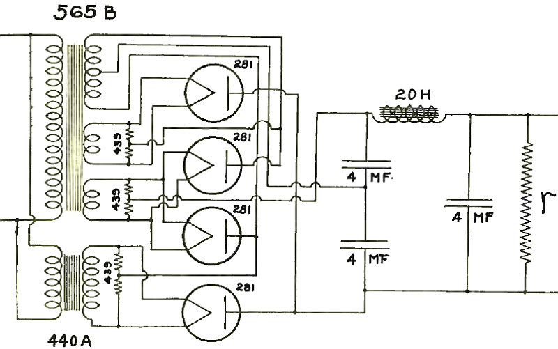
Fig. 1. Full Wave Voltage Doubling Rectifier Filter Circuit.
Article: Technical Briefs.
"To meet the demand for a 1000 to 1500 volt amplifier system capable of supplying 170 milliamperes for amature transmitters and power amplifiers the General Radio Co. recommends the arrangement and equipment shown in Fig. 1. It uses four 281 type half - wave rectifier tubes to give a full wave voltage doubling circuit, one of these tubes being rated to deliver 85 m.a. at 700 volts..."
(Radio for January, 1929)
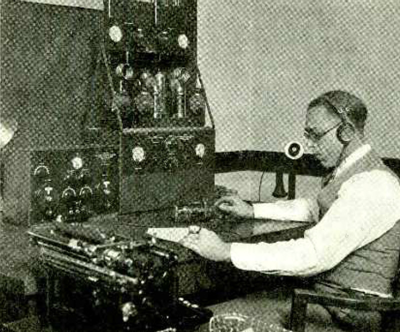
Lecher Wires, Hartley Oscillator and Wavemeter.
Article: With the Amateur Operators - LECHER WIRES AND STANDING WAVES.
"Under the new radio regulations of the Washington Convention it is important that every amateur transmitter be tuned accurately within the assigned wave bands. This means that the amateur must buy or build and calibrate an accurate instrument for the purpose. The ideal method would be to build a separate wave meter for each of the different amateur bands. The cost of having four or five separate meters calibrated is quite beyond the means of the average amateur. The Lecher wire method of calibrating wave meters without the use of a standard is offered as a solution to the problem. An accuracy of 1/5 of 1% is not difficult to attain with it..."
(Radio for January, 1929)
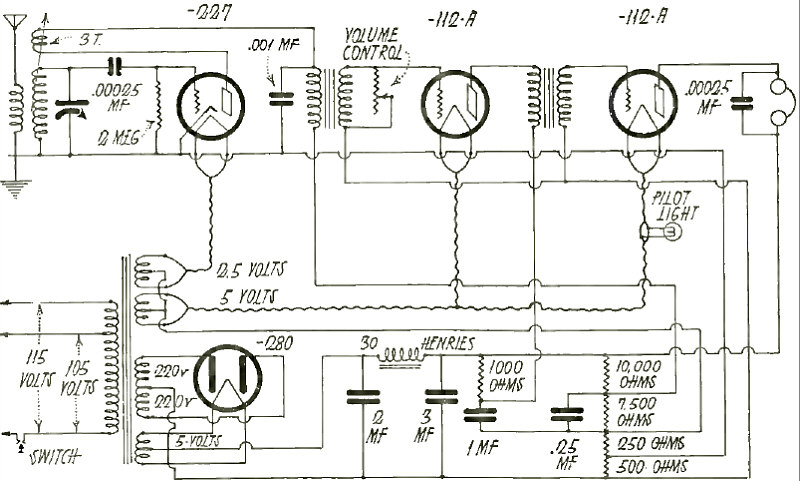
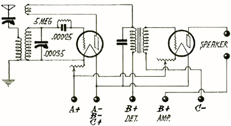
Circuit of Three -Tube Local Program Receiver.
Article: Inside Stories of Factory Built Receivers.
"... this receiver being primarily designed for the reception of local programs, and hence is less expensive than the six -tube model. It consists of a three -circuit tuner, with regenerative detector, and two stages of transformer coupled audio, with 112 -A power tube, and a type 80 full -wave rectifier in the power plant. The latter is practically the same as for the six -tube model, except in the arrangement of the B voltage supply taps in the resistance group. The chassis has the same appearance as the six -tube model, and the front panel is identical with that of the larger set..."
(Radio for January, 1929)
Rear View of Chassis of Six -Tube Set.
Article: Inside Stories of Factory Built Receivers.
(Radio for January, 1929)
Circuit of Six -Tube Acme Receiver.
Article: Inside Stories of Factory Built Receivers.
(Radio for January, 1929)
There Is a REMLER KIT for Every Purpose - The REMLER 29.
Advertisement.
(Radio for January, 1929)
One of Wilkins' 33.5 Meter Transmitters.
(Radio for January, 1929)
PAM 16 or 17 Amplifier.
Advertisement.
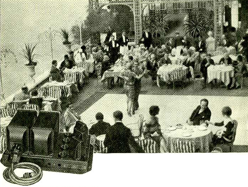
"Here's a Seat at the Cabaret.
Enjoy your favorite orchestra as if it were present; recreate the renditions of famous artists so nothing is left for the ear to desire, and perfect the "atmosphere" of beautiful surroundings - by using the Samson PAM Amplifier. A phonograph or a radio set may be used in conjunction with these amplifiers, to produce music in one or many rooms -or out -of- doors. And remember -wide awake cabaret owners are using PAM amplifiers to produce music and more business in their restaurants...."
(Radio for February, 1929)
500-Watt, 32.4 Miter Transmitter at Control Station KRG.
Article: Radio Marketing for the Farmer.
"A Central California farmer was recently offered 60 cents a bag for his crop of onions by an agent who seemed very eager to buy. Suspecting that the buyer was armed with a superior knowledge of the marketing situation, the farmer got in touch with the Federal -State Marketing Service radio station, KRB, at Salinas, California, asking for a report on crops and current prices. KRB referred the question to the San Francisco station, KRG, where trained market analysts investigated the onion situation and reported at once that onion crops had been badly damaged in other sections and that the demand was on an upward trend. KRG sent the report back to Salinas and the farmer, no longer at a disadvantage, refused the offer of 60 cents, later selling at $1.65..."
(Radio for February, 1929)
Power Panel and Receiver at KRG.
Article: Radio Marketing for the Farmer.
(Radio for February, 1929)
100-Watt Field Station KRM.
Article: Radio Marketing for the Farmer.
(Radio for February, 1929)
3/4 Meter Parabolic Reflector at 6BX.
Article: With the Amateur Operators - PARABOLIC REFLECTORS.
"The gain in power radiated in a given direction with a simple parabolic reflector is of the order of 4 times that obtained with a single vertical wire favoring no particular direction. And because the expense entailed by the addition of the few wires and insulators necessary to this directional antenna and the installation of more powerful equipment to secure the same fourfold increase in result, the parabolic reflector is of great value to the transmitting amateur who must of necessity use low power. Parabolic reflectors, at the shorter wavelengths, are small enough to be conveniently used in most amateur stations. They are simple in construction and more effective than many of the more elaborate systems..."
(Radio for February, 1929)
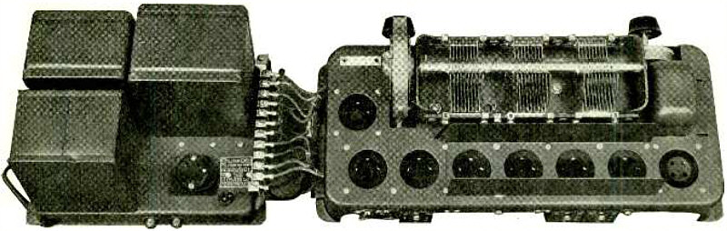
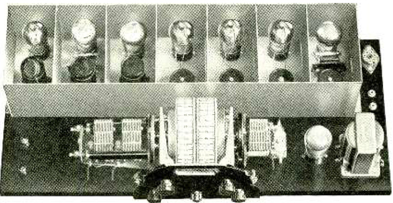
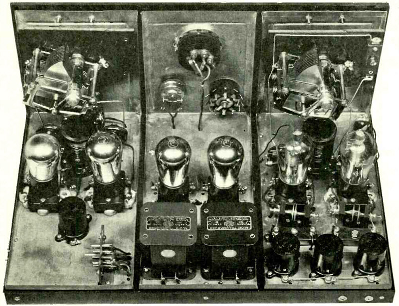
Chassis of Radiola 60.
Article: Inside Stories of Factory Built Receivers - RADIOLAS 60, 62 AND 64.
"R. C. A. Radiola 60 is a socket powered receiver employing an 8 tube superheterodyne circuit and a full wave rectifier. With the exception of the UX -280 rectifier tube and the UX -171A in the last audio stage, UY -227s are used throughout, and all plate, grid and filament voltages are supplied by the socket power unit which is a part of the set, built on a separate chassis but mounted in the cabinet at the right of the receiver assembly..."
(Radio for February, 1929)
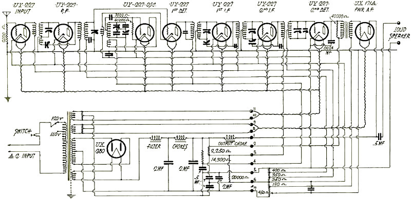
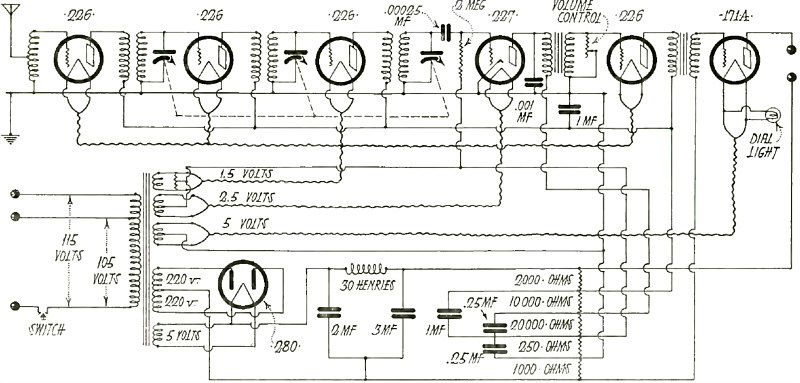
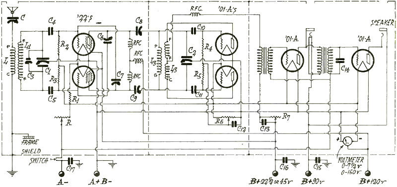
Circuit Diagram of Radiola 60.
Article: Inside Stories of Factory Built Receivers - RADIOLAS 60, 62 AND 64.
(Radio for February, 1929)
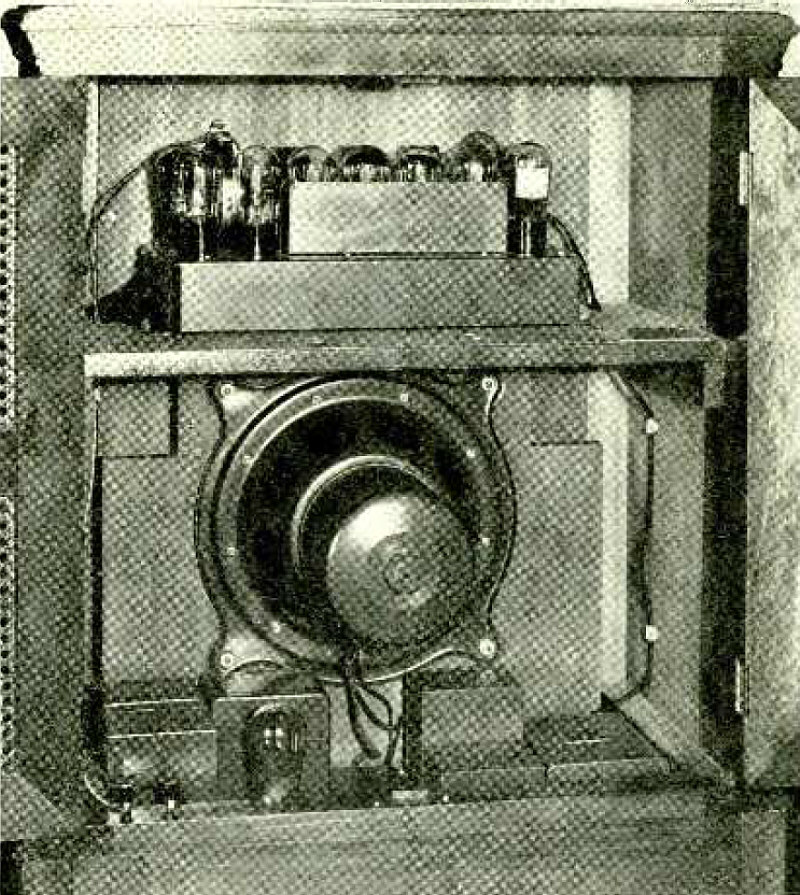
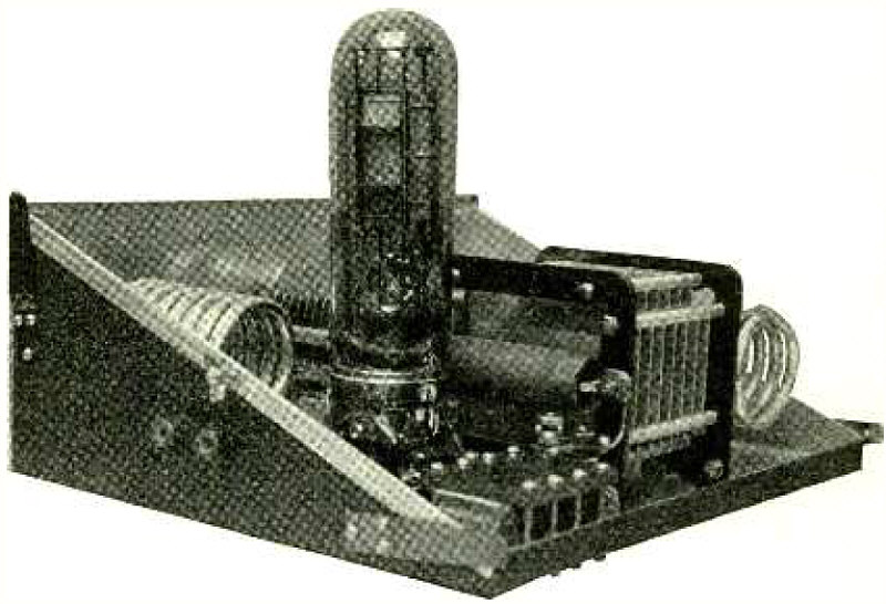
Rear View of Radiola 62.
Article: Inside Stories of Factory Built Receivers - RADIOLAS 60, 62 AND 64.
(Radio for February, 1929)
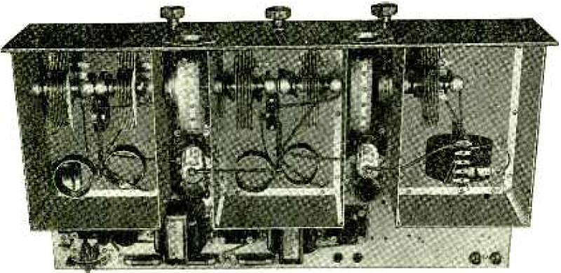
Top View of Hammarlund- Roberts "Hi -Q 29".
Article: Radio Kit Reviews - HAMMARLUND- ROBERTS MASTER ttHI -Q 29".
"This kit is designed to facilitate the assembly of a high -grade receiver which has maximum sensitivity, selectivity and fidelity of tone reproduction with five d.c. 4 tubes. Extreme sensitivity is secured from the great amplification provided by two screen -grid tubes in the r.f. amplifier. Great selectivity without cutting of side -bands is attained by special tuned -grid and tuned - plate r.f. circuits which afford a band -pass filter. Great volume without distortion results from the use of high -grade audio transformers and a power tube..."
(Radio for February, 1929)
Bosworth power amplifier.
Article: Radio Kit Reviews.
"Bosworth power amplifiers for radio and phonograph reproducers are made in a number of different sizes for various purposes. Model Amp. 1, which is illustrated herewith, uses a '26 tube in the first and two '71 tubes in push -pull for the last stage, with one '80 rectifier tube; lA also has voltage taps for A, B, and C supply for a.c. sets. Model Amp. 2 and 2A, use a '26 tube in the first and a '50 tube in the last stage, with two '81 rectifier tubes. Models Amp. 3 and 4 are for use in auditoriums, with two or four speakers respectively, both being three -stage amplifiers with a '27 tube in the first and two '27's push -pull in the second stage. The former uses two '50 tubes push -pull in the third stage with two '81 tubes and the latter four '50 tubes multiple push -pull and four '81 rectifier tubes. Model Mic, is a battery - operated two -stage outfit, for public address work."
(Radio for February, 1929)
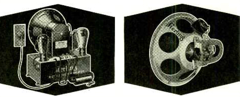
Sterling Accessories for Better Tone.
Advertisement.
Left: Powerful Dynamics. Right - Super-Magnetics.
(Radio for February, 1929)
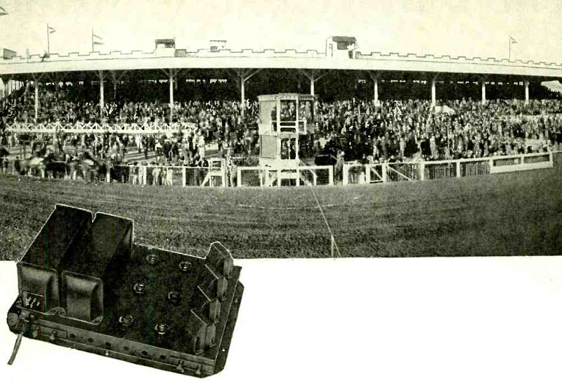
PAM 19.
Advertisement: Set the Pace With a "PAM".
"BANG ! They're off like a flash -and at Tia Juana (pictured above) the spectators, wherever located about the track, know the whole story because they are informed by means of a PAM 19 and MIK 1. Every race track is a prospect for you and remember this is but one of a thousand applications for "PAM" amplifiers which are keeping professional set builders and service men busy throughout this country. There is no closed season for "PAM" Amplifiers."
(Radio for March, 1929)
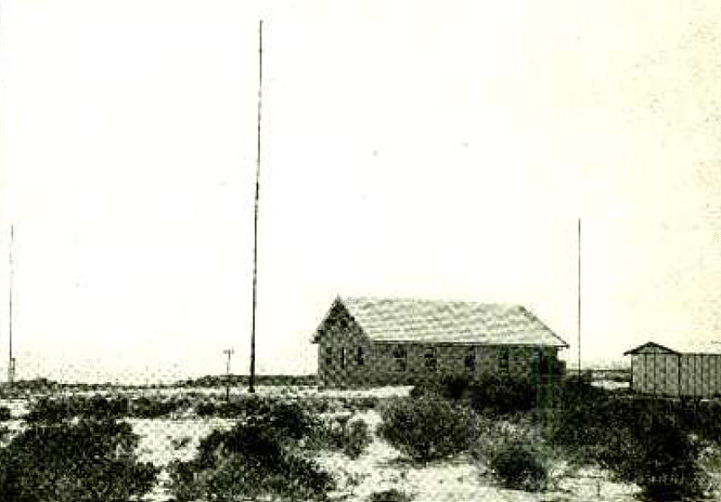
A. W. A. Receiving Center at La Perouse, near Sydney, Australia.
Article: Australian Short-Wave Radio.
"Radio telephony between Australia and the United States, and between Australia and Java became an accomplished fact with the inauguration of service on November 1, by Amalgamated Wireless (A'sia) Ltd. This service is maintained by means of a 20 -k.w. short -wave transmitter at Pennant Hills, and by receiving equipment at La Perouse, both of these stations being connected by wire telephone with the control office at Sydney. This equipment has communicated directly with Bandoeng, Java, and WGY at Schenectady, N .Y., and will eventually be used for telephoning to London..."
(Radio for March, 1929)
20 K.W. Short -Wave Transmitter at 2ME.
Article: Australian Short-Wave Radio.
"... The 20 k.w. transmitter feeds into one of the aerials supported by the 400 - ft. mast at Pennant Hills, 14 miles from Sydney..."
(Radio for March, 1929)
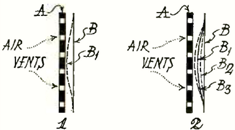
(1) - Unilateral Speaker without Polarizing Voltage. (2) - Unilateral Speaker with Polarizing Voltage.
Article: The Electrostatic Loudspeaker - An Explanation of the Fundamental Principles of the Unilateral and Bilateral Types of Condenser Speakers.
"The condenser or electrostatic type of loudspeaker is the latest development of intensive research by radio -acoustic engineers. They are continually trying to get greater fidelity in tone production and greater energy from all types of electrophonic devices. Nor do they claim that the electrostatic type is the last word in speaker design, any more than were the electromagnetic and the electrodynamic types. Audio -frequency currents and voltages may yet be converted into sound of greater fidelity to the original in half a dozen other ways, including magneto -striction and corona discharge. But the electrostatic type has graduated from the laboratory and is now a commercial product..."
(Radio for March, 1929)
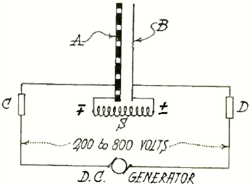
(F Method of Applying Polarizing Voltage to Unilateral Speaker (Fig. 3).
Article: The Electrostatic Loudspeaker - An Explanation of the Fundamental Principles of the Unilateral and Bilateral Types of Condenser Speakers.
"... The polarizing voltage is best applied through high resistances of the order of .5 to 2 megohms. Theoretically, an a.f. choke of 30 -50 henries would be efficient in keeping the speaker permanently charged and yet in preventing its variations of potential, as it vibrated, from expending energy in the circuit supplying this polarizing voltage. In Fig. 3 such chokes are indicated at C and D. As their effect is uneven over the audio range, they would permit the bass notes to be lost through the d.c. generator or B battery, while the high notes would come through normally: the chokes would prevent their leaking away..."
(Radio for March, 1929)
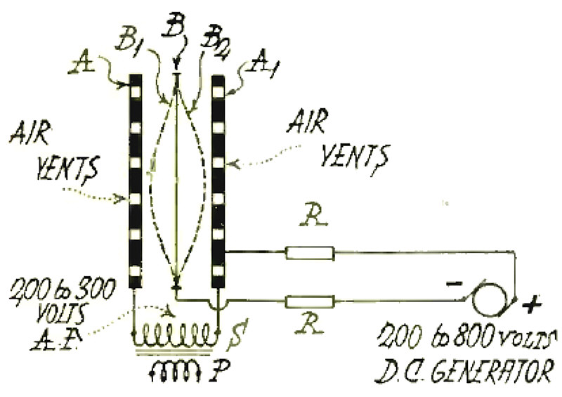
Bilateral Speaker.
Article: The Electrostatic Loudspeaker - An Explanation of the Fundamental Principles of the Unilateral and Bilateral Types of Condenser Speakers.
"... Figure shows a bilateral speaker in which the two fixed plates A and A1 are connected to the secondary of an audio transformer whose primary is in the output circuit of a 200 -400 volt a.f. stage. The movable element B is accurately adjusted so as to be exactly
midway between and parallel to A and A1, whose inner faces are carefully machined to plane surfaces. A polarizing voltage is ordinarily used with a bilateral speaker to strengthen B's response to a.f. voltage, although it is not necessary to prevent doubled frequencies,
which cannot occur if B is exactly midway between A and A1."
(Radio for March, 1929)
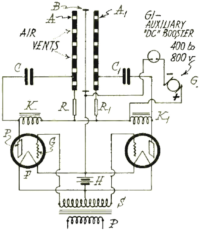
Diagram of Connections for Bilateral Speaker.
Article: The Electrostatic Loudspeaker - An Explanation of the Fundamental Principles of the Unilateral and Bilateral Types of Condenser Speakers.
"... Fig. 6 is the circuit diagram for an oscilloplane type of electrostatic speaker with two '50 tubes in push pull. Plate voltage for the tubes and the polarizing voltage for the speaker are supplied from a 400 -800 volt d.c. source. The polarizing voltage is supplied through resistances R and R1, which are from 1 to 2 megohms each. The plate voltage is supplied through the chokes K and K1f which are from 25 to 50 henries each and so placed that a.f. currents cannot pass through them, but are bypassed through 2.4mfd. condensers C and C1."
(Radio for March, 1929)
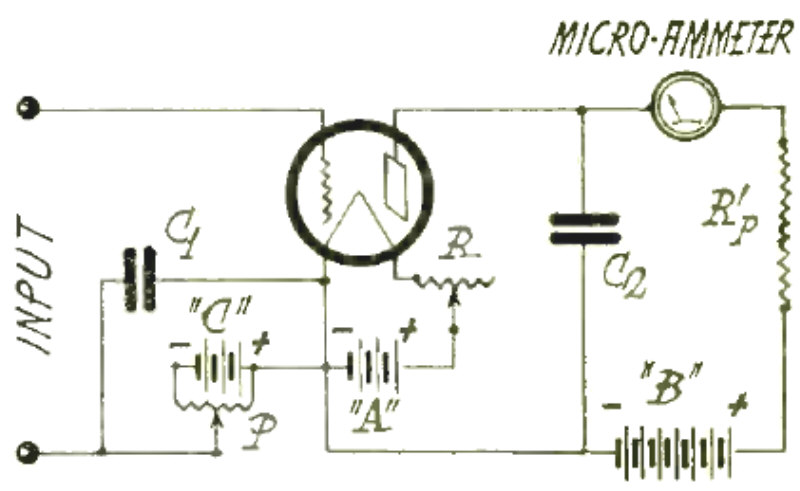
Vacuum Tube Voltmeter Having Zero Frequency Error.
Article: Vacuum Tube Voltmeter Design.
"Perhaps no instrument has contributed more toward making the scientific design of radio receivers a practical reality than has the vacuum tube voltmeter. It has made possible the measurement of feeble radio and audio-frequency voltages that previously were guessed at. It comes the closest to the ideal voltmeter that man has been able to produce, drawing hardly more current than can leak across a piece of insulation between two binding posts..."
(Radio for March, 1929)
Circuit Diagram of Vacuum Tube Voltmeter.
Article: Vacuum Tube Voltmeter Design.
(Radio for March, 1929)
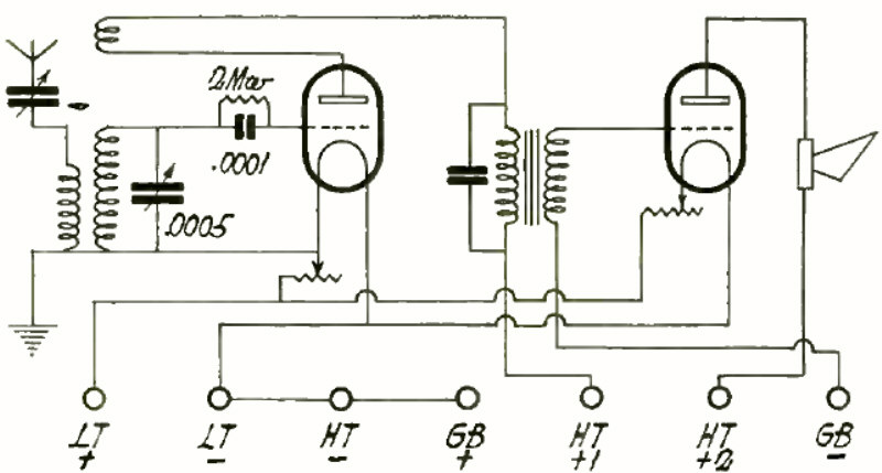
American Version.
Article: Translating Foreign Circuit Diagrams.
"Anyone who is cursed with the job of wading through the technical radio literature of the world, soon reaches a state of confusion where he has no idea whether the thing with a light in it is a "lamp," or a "tube," or a "valve "; whether it works from A and B batteries, or from Low and High Tension batteries, or from Heating and and Anode batteries; and uses Reaction, or Regeneration, or Back -coupling. As a result, one gets into the habit of reading the diagrams rather than the text. Even here, all is by no means plain sailing, as the four diagrams show. Although it may not be evident, they all represent the same circuit..."
(Radio for March, 1929)
English Version.
Article: Translating Foreign Circuit Diagrams.
(Radio for March, 1929)
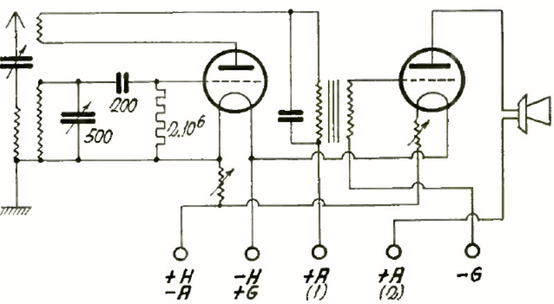
Germnan Version.
Article: Translating Foreign Circuit Diagrams.
(Radio for March, 1929)
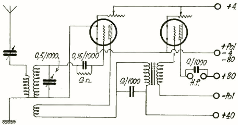
French Version.
Article: Translating Foreign Circuit Diagrams.
(Radio for March, 1929)
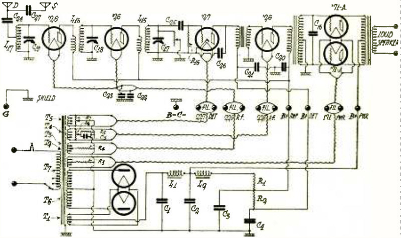
Circuit Diagram of Federal Type H Ortho -Sonic Receiver.
Article: Inside Stories of Factory Built Receivers - FEDERAL ORTHO -SONIC TYPE H RECEIVER.
"This set uses six tubes, two '26's for r.i. amplification, one '27 for detector, one '26 for the first audio and two '71 -A power tubes in push -pull for the second audio..."
(Radio for March, 1929)
THE CROSLEY RADIO CORPORATION, CINCINNATI, OHIO.
Advertisement.
(Radio for March, 1929)
Helping WRNY to keep its fine reputation.
"Station WRNY, Hotel Roosevelt, New York, is known for its clarity. The engineers here, as in other large broadcasting stations, depend upon PYREX Insulators as an essential to long range and protection of tone quality against retransmission noises from adjacent conductors..."
(Radio for March, 1929)
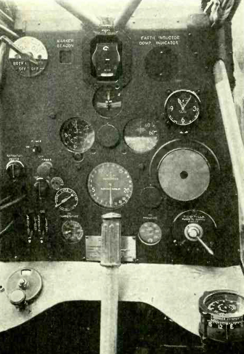
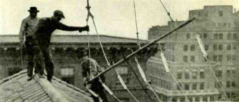
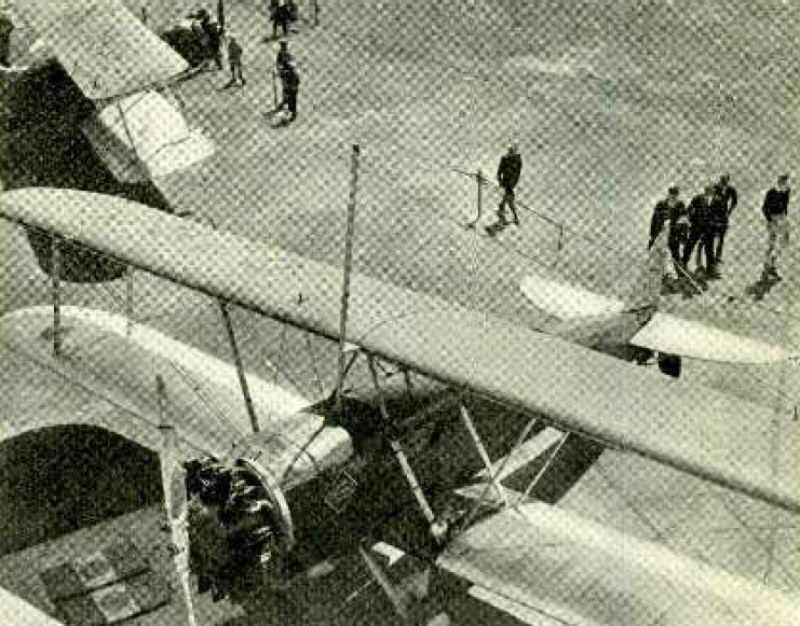
The Pilot's Instrument Board.
Article: A Night and Fog - Flying Radio Laboratory.
"The research laboratory takes wings! The problems incident to aircraft communication and the guidance of airplanes by radio may now be studied during flights. A plane outfitted by the Radio Laboratory of the Bureau of Standards enables the research worker to emerge from academic walls and subject radio instruments and other safety devices to the practical tests of navigation. Intended primarily for experimenting with the radio beacon system during night flying and for flying and landing in fog, this laboratory on wings figuratively and literally lifts the scientist from an atmosphere of theory to an air of performance -where instrumental equipment either meets the rigid tests of service or fails under the stress of action..."
(Radio for April, 1929)
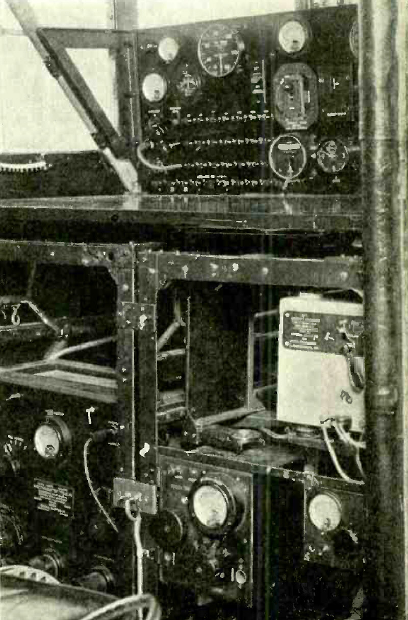
The Observer's Desk.
Article: A Night and Fog - Flying Radio Laboratory.
(Radio for April, 1929)
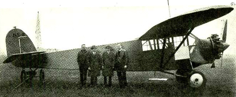
The Flying Radio Laboratory and Its Developers.
Article: A Night and Fog - Flying Radio Laboratory.
(Radio for April, 1929)
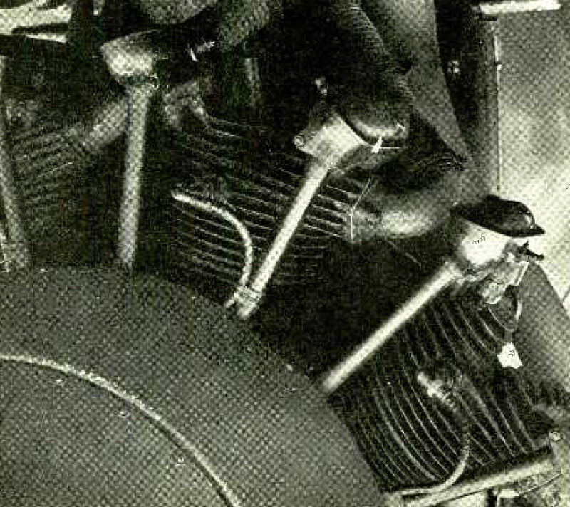
The Shielded Ignition System.
Article: A Night and Fog - Flying Radio Laboratory.
(Radio for April, 1929)
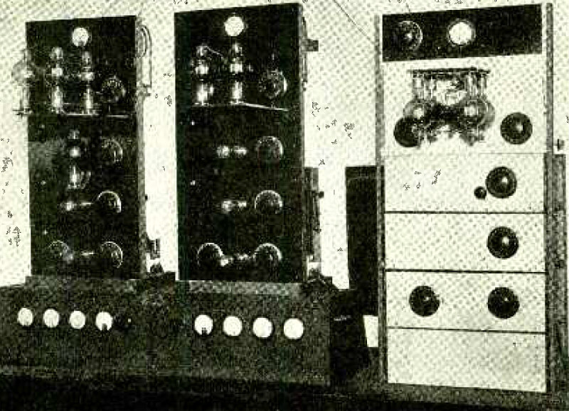
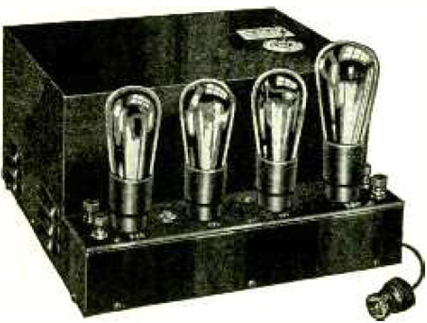
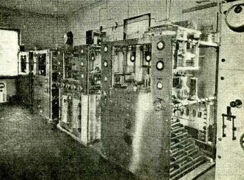
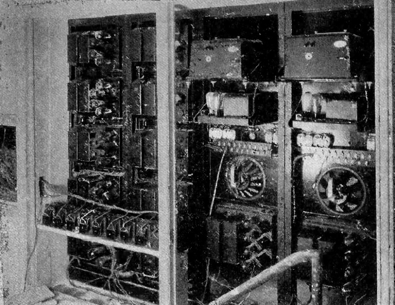
Three Crystal- Controlled Transmitters at W8CAU -W8YX, 400 -watt, 40 -meter Telegraph, 200 -watt, 20 -meter Telegraph, 400 -wail, 80 -meter Telegraph and Telephone.
Article: Remote Control by Radio - How a 400 -Watt Transmitter Is Operated Without Wire Connection From Several Five -Watt Substations.
"If it were light enough, one could see an array of radio apparatus around the room: a three -tube receiver and accessories on the table to the rear ; power -panels with switches, meters, and contactors, at the side ; and in front, two short -wave transmitters above a meter and transformer cabinet, and a third transmitter at the side. If it were light enough -but the only light comes weakly from the rectifier tubes -the B-eliminator kenotron, and over in the corner, a tungar. They burn, as do the three receiver tubes, day and night..."
(Radio for April, 1929)
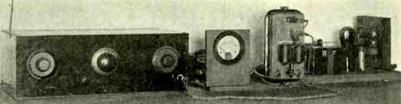
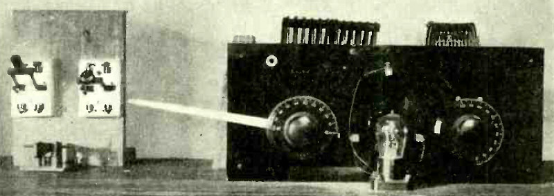
Remote Control Receiving Equipment - Shielded Receiver, D.C. Milliammeter, Control Relay, and "B" Eliminator.
Article: Remote Control by Radio - How a 400 -Watt Transmitter Is Operated Without Wire Connection From Several Five -Watt Substations.
(Radio for April, 1929)
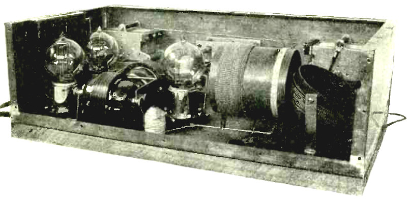
Rear View of Remote Control Receiver.
Article: Remote Control by Radio - How a 400 -Watt Transmitter Is Operated Without Wire Connection From Several Five -Watt Substations.
(Radio for April, 1929)
Typical Substation Control Transmitter
Article: Remote Control by Radio - How a 400 -Watt Transmitter Is Operated Without Wire Connection From Several Five -Watt Substations.
(Radio for April, 1929)
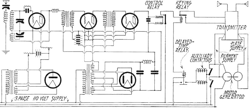
Circuit Diagram of Receiving and Starting Equipment
Article: Remote Control by Radio - How a 400 -Watt Transmitter Is Operated Without Wire Connection From Several Five -Watt Substations.
(Radio for April, 1929)
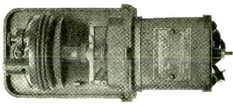
The Heart of the System, an Air -Bellows Delayed -Time Relay
Article: Remote Control by Radio - How a 400 -Watt Transmitter Is Operated Without Wire Connection From Several Five -Watt Substations.
(Radio for April, 1929)
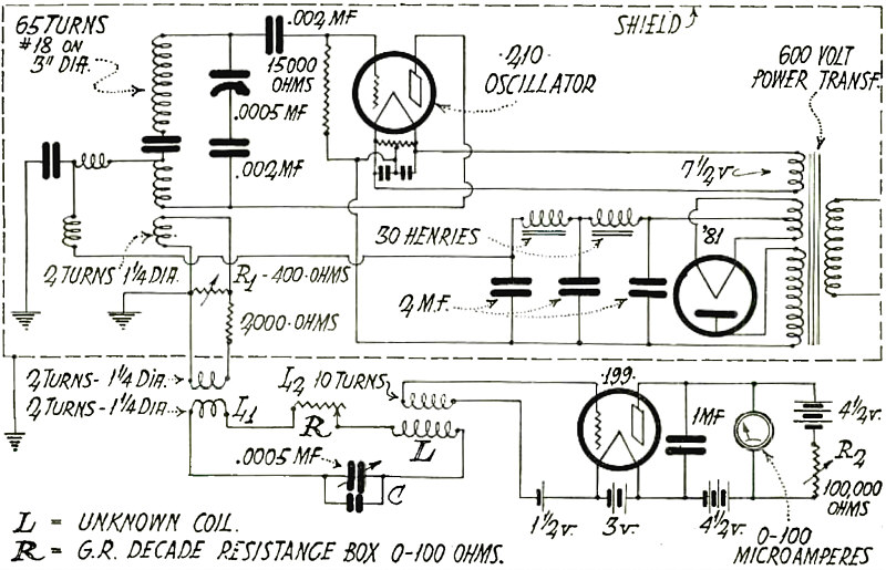
Coil Measuring Circuit.
Article: R. F. Coil Resistance Measurements.
(Radio for April, 1929)
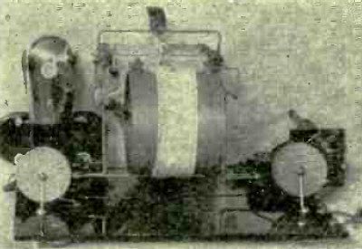
Bell Laboratory Filin Recording Machine.
Article: How the Movies Are Made to Talk - A Concise Description of the Movietone, Photophore and Vitaphone Methods of Recording and Reproducing.
"The success of the talking moving picture is due primarily to the perfection of the electrical reproduction of sound which has been accomplished in the radio telephone transmitter and receiver. Without this recent perfection neither the desired volume and tone quality nor the delicacy of control necessary for the synchronization of sound and sight would have been possible. Knowledge of the methods employed give the radio experimenter new ideas for improving present radio - phonograph combinations and for anticipating the advent of sound- picture equipment in the home, whether using film directly or receiving it by radio..."
(Radio for May, 1929)
Photoelectric Cell Used in Bell Laboratory Machine.
Article: How the Movies Are Made to Talk - A Concise Description of the Movietone, Photophore and Vitaphone Methods of Recording and Reproducing.
(Radio for May, 1929)
Front View of Marshall Receiver.
Article: The Marshall Short -Wave Receiver - Constructional Details and Operating Suggestions for an Experimental Model.
"Since the announcement of the Marshall receiver in November, 1928, RADIO there have been many requests for information regarding the construction and operation of this set, so one was constructed from available parts. Although the results are not revolutionary they have been more than satisfactory, especially for the broadcast listener who can spend a few moments in tuning in a station, or the amateur or commercial operator who handles a lot of traffic with a comparatively few stations. But the amateur who desires speedy selection of many stations spread out over a certain band will probably not find the Marshall exactly suited to his needs..."
(Radio for May, 1929)
Circuit Diagram of Marshall Short- Wave Receiver.
Article: The Marshall Short -Wave Receiver - Constructional Details and Operating Suggestions for an Experimental Model.
(Radio for May, 1929)
Rear View, Showing Layout and Construction of Cans.
Article: The Marshall Short -Wave Receiver - Constructional Details and Operating Suggestions for an Experimental Model.
(Radio for May, 1929)
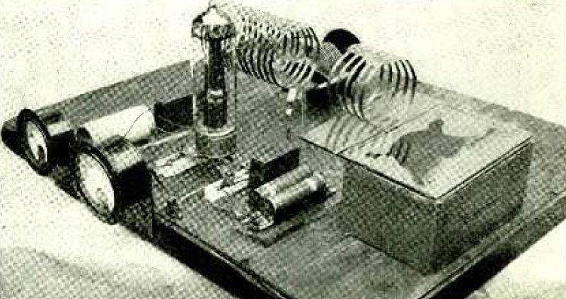
Inexpensive 50 - Watt Transmitter.
Article: With the Amateur Operators - A FIFTY -WATT SHORT -WAVE TRANSMITTER.
"With comparatively little expense, it is possible to construct a 50 -watt transmitter from odds and ends easily secured or already available. The tube, meters and transformers are the real essentials; the rest of the set is the result of a combination of inventive ability, influential friends and luck ; and every amateur has all three. With the aid of the illustration and Fig. 1, construction is quite simple..."
(Radio for May, 1929)
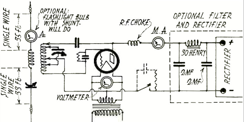
Circuit Diagram of 50- Watter (Fig. 1)
Article: With the Amateur Operators - A FIFTY -WATT SHORT -WAVE TRANSMITTER.
(Radio for May, 1929)
Reproducer Detail.
Article: An Outdoor Audio Amplifier.
"The amplifier equipment for a theater or large hall requires less power than is ordinarily assumed. A factory -built 2 -stage amplifier with a pair of '10 tubes in the output and an efficient dynamic unit with a paper horn baffle has proven sufficient, in practice, to serve a 1500 -seat house. Not more than one -fourth of the possible undistorted volume from this little amplifier was required for the satisfactory reproduction of music with 1000 people in the seats..."
(Radio for May, 1929)

Reproducer.
Article: An Outdoor Audio Amplifier.
(Radio for May, 1929)
Circuit Diagram of Outdoor Audio Amplifier.
Article: An Outdoor Audio Amplifier.
(Radio for May, 1929)
Completed Amplifier.
Article: An Outdoor Audio Amplifier.
(Radio for May, 1929)
Power and Tone. Model GA-20
Advertisement.
"This powerful three -stage amplifier uses two UX -250 tubes, two UX -226 tubes and one UY -227 tube. The last two stages are connected in push -pull. It will deliver approximately 15 watts of undistorted energy to the speaker. An unusually good frequency characteristic is obtained from this device by the liberal use of filters in the plate and grid circuits of the tubes."
(Radio for May, 1929)
Picking Out Imperfect Tubes.
Advertisement.
"Picking out imperfect tubes is easy with our Type 443 Mutual- Conductance Meter. It shows up incorrect spacing of the elements as well as faulty filament emission."
(Radio for May, 1929)
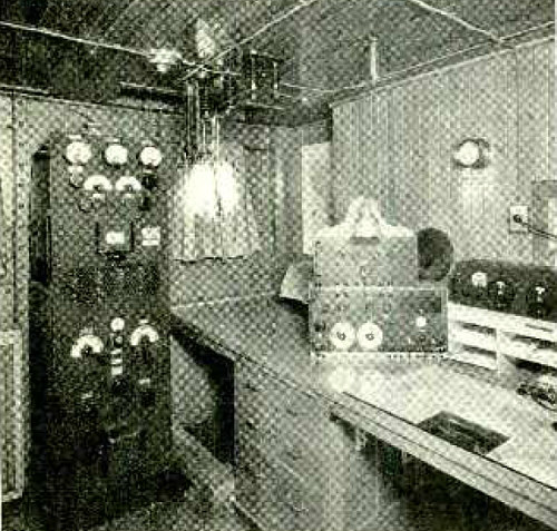
Long Wave Equipment on WSBW. Short Wave Receiver at Right.
Article: Radio Equipment of S. S. Virginia, WSBW.
"The S. S. Virginia and her sister ship the California are the largest electrically propelled commercial vessels in the world. With a length of 613 feet, the Virginia has a beam of 80 ft., a depth of hull of 52 ft. and a total depth of 100 ft. from upper deck to keel. She has a displacement of 31,000 tons, travels at a speed of 21g miles per hour, carrying 800 passengers and 8500 tons of freight. And, getting back to our regular line of thought, she is in communication with both American coasts day and night..."
(Radio for June, 1929)
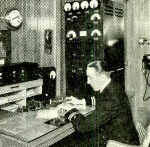
Short Wave Receiver and Transmitter. T. Jay Byrne at the "Bug".
Article: Radio Equipment of S. S. Virginia, WSBW.
(Radio for June, 1929)
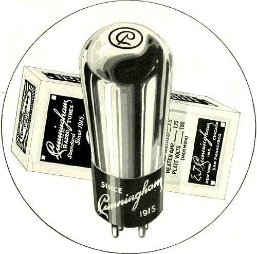
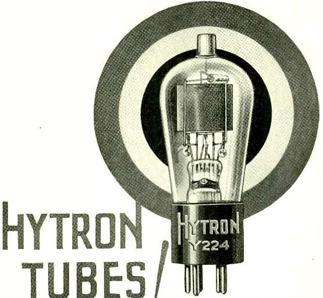
Cunningham Radio Tubes.
Advertisement.
"Be guided by a name that has meant absolute tube integrity for the past fourteen years. The name is Cunningham choice of the American home."
(Radio for July, 1929)
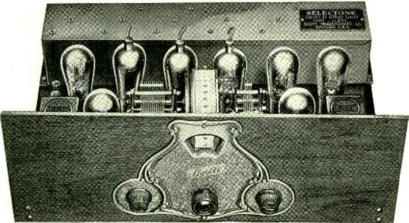
The New Scott A.C. Shield Grid 10.
Advertisement.
(Radio for July, 1929)
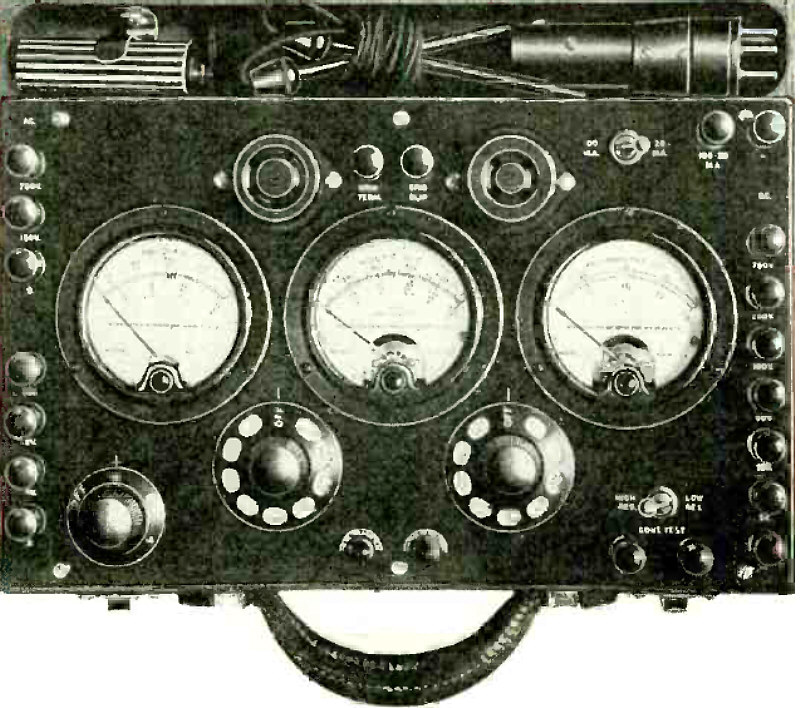
The New Radio Set Tester.
Advertisement.
"The radio industry is familiar with the Weston Model 537 Radio Set Tester -for A. C. and D. C. receivers. Service men hailed it with great acclaim a year ago, noting its many advantages over the Weston Model 519 -for D. C. only. And NOW -here is another great advance- the Weston Model 547- incorporating many additional features to meet the service testing requirements of radio's latest developments..."
(Radio for July, 1929)
Advertisement.
(Radio for July, 1929)
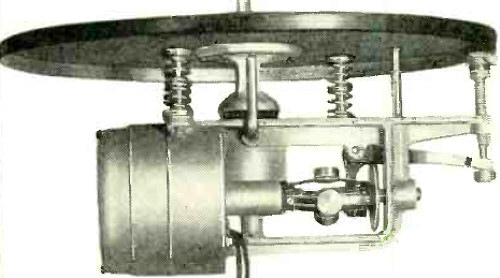
New Pacent Induction Type Phonograph Motor.
Advertisement.
(Radio for July, 1929)
New Pacent Induction Type Phonograph Motor.
Advertisement.
(Radio for July, 1929)
Pacent Electrovox Chassis.
Advertisement.
(Radio for July, 1929)
Chassis of Atwater Kent Screen -Grid Receiver.
Article: Booth Report of Exhibits at R. M. A. Show.
"The Atwater Kent screen grid receiver has two '24 tubes coupled to bank -wound transformers in the r.f. stages, a '27 tube with grid bias in the detector stage, a '27 tube with resistance coupling in the first audio stage, and two '45 tubes in push -pull in the second audio stage. The chassis is completely shielded, all but a few inches of wire being in a shielded sub -base compartment."
(Radio for July, 1929)
Plane Equipped With Vertical Antenna Mast and Wire to Tail.
Article: Radio Telephony Aloft - A Description of a Successful Plane -to -Plane and Plane -to- Ground Communication System.
"The need for radio telephone equipment on aircraft has long been recognized by the leading authorities in the air transportation business. With the rapid increase in passenger travel on the transcontinental air lines it has become necessary for the airplane to be in constant touch with the ground in order to maintain schedules and insure the safety of passengers and equipment..."
(Radio for July, 1929)
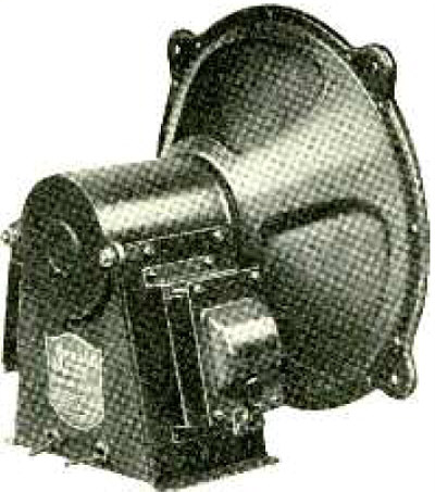
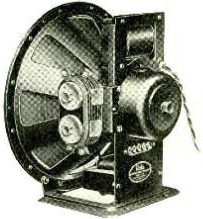
Jensen Model D -7 A.C. Concert Dynamic Speaker.
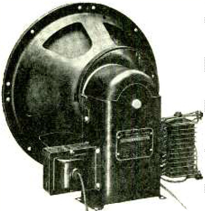
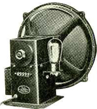
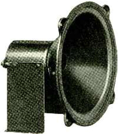
Article: Facts About the New Loud Speakers.
(Radio for July, 1929)
Magnavox Models 401, 403 and 405.
Article: Facts About the New Loud Speakers.
(Radio for July, 1929)
Rola Model "R -A.C." Reproducer.
Article: Facts About the New Loud Speakers.
(Radio for July, 1929)
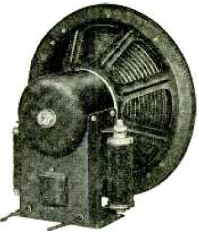
Jensen Model D -7 D.C. Concert Dynamic Speaker.
Article: Facts About the New Loud Speakers.
(Radio for July, 1929)
Rola Model "C -110 A.C." Reproducer.
Article: Facts About the New Loud Speakers.
(Radio for July, 1929)
Utah 12.5 -in. Cone Unit.
Article: Facts About the New Loud Speakers.
(Radio for July, 1929)
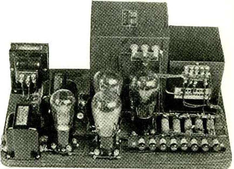
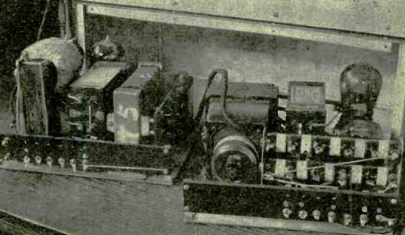
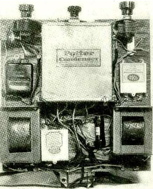
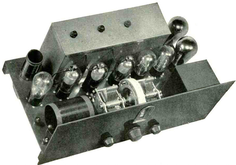
Thordarson R -245 Amplifier and Power Supply.
Article: New Receiver and Amplifier Kits - THORDARSON R -245 AMPLIFIER AND POWER SUPPLY.
"The Thordarson R -245 power compact has been designed for use with the '45 tubes. The transformer has a 5 -volt secondary for the '80 rectifier tube, a 2.5 -volt secondary for the '45s and the '27, if a preceding stage is employed, and a high- voltage secondary for the plate supply. All are center -tapped. The compact also houses two filter chokes..."
(Radio for July, 1929)
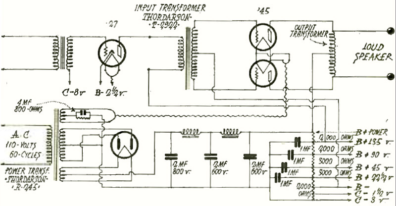
Circuit Diagram of Thordarson R -245 Amplifier.
Article: New Receiver and Amplifier Kits - THORDARSON R -245 AMPLIFIER AND POWER SUPPLY.
(Radio for July, 1929)
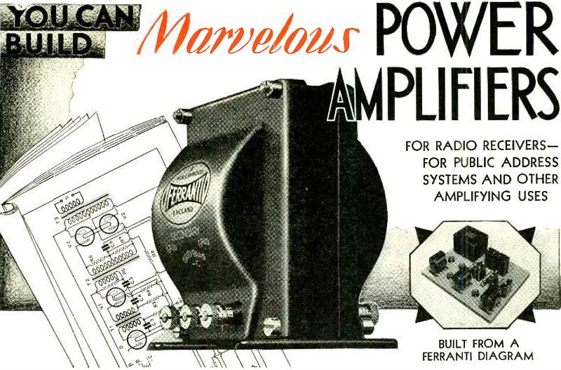
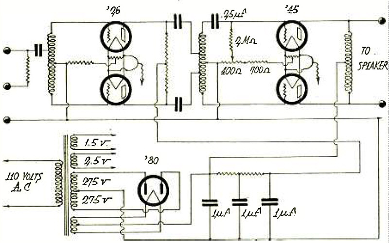
Push -Pull Power Amplifier Employing Resistance- Capacity Filter.
Article: New Receiver and Amplifier Kits - A PUSH -PULL POWER AMPLIFIER WITH TYPE '45 TUBES.
"Recommendations for the construction of a two -stage a.c. amplifier and power supply with type '45 tubes in push -pull in the power stage have been made by Ferranti Inc. for use with 110 volts, 60 cycle a.c. supply..."
(Radio for July, 1929)
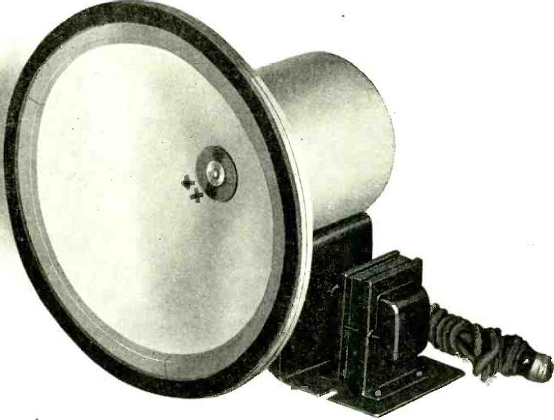
Announcing the NEW WRIGHT - DE COSTER REPRODUCER.
Advertisement.
(Radio for July, 1929)
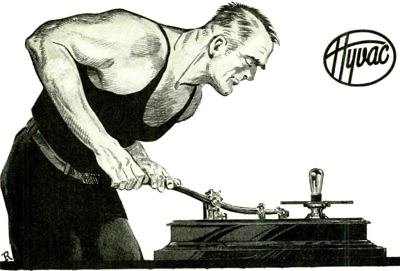
One of the earliest known methods of securing vacuum.
Advertisement.
"HYVAC - the super - vacuum radio tube. Tremendous strides have been made in the manner of creating vacuum since the primitive method illustrated above, and to this progress the radio tube industry largely owes its present high standard of perfection..."
(Radio for July, 1929)
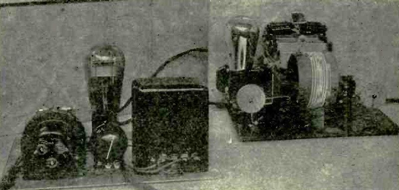
Transmitter at W2ALU.
Article: With the Amateur Operators - ACCOMPLISHMENTS AT W2ALU.
"W2ALU is a 1000 -watt station operated by John B. Knight and Fred M. Link in their apartment at 583 Riverside Drive, New York City."
(Radio for August, 1929)
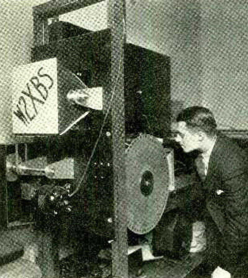
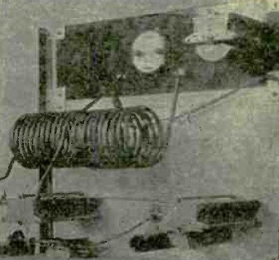
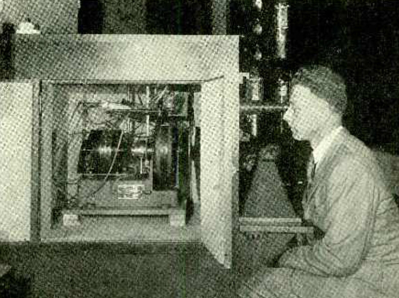
Picture Target and Monitor Scanning Disc at W2XBS.
Article: TELEVISION AT W2XBS.
"The experimental broadcasting station of the Radio Corporation of America, call letters W2XBS, at 411 Fifth Avenue, New York City, is f requently used for conducting basic experiments in television transmission and reception. Its experimental activities have followed several years of television research and development by engineers of the General Electric Company, under the direction of Dr. E. F. W. Alexanderson, and by television specialists of the Westinghouse Electric and Manufacturing Company, under the supervision of Dr. Frank Conrad."
(Radio for August, 1929)
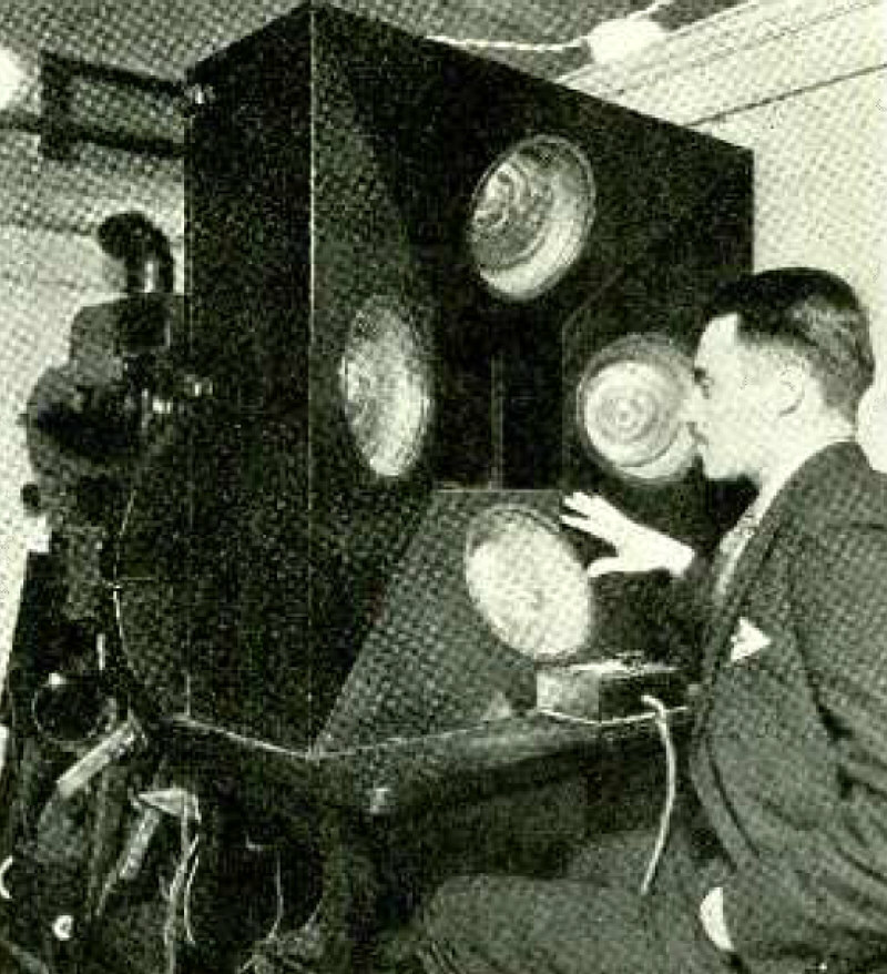
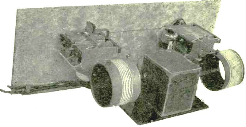
Photo -Cells of Television Scanner at W2XBS.
Article: TELEVISION AT W2XBS.
(Radio for August, 1929)
Advertisement.
(Radio for September, 1929)
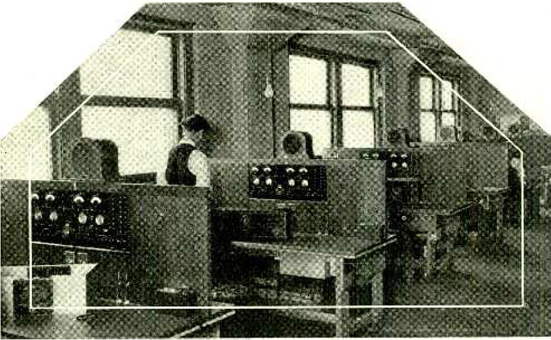
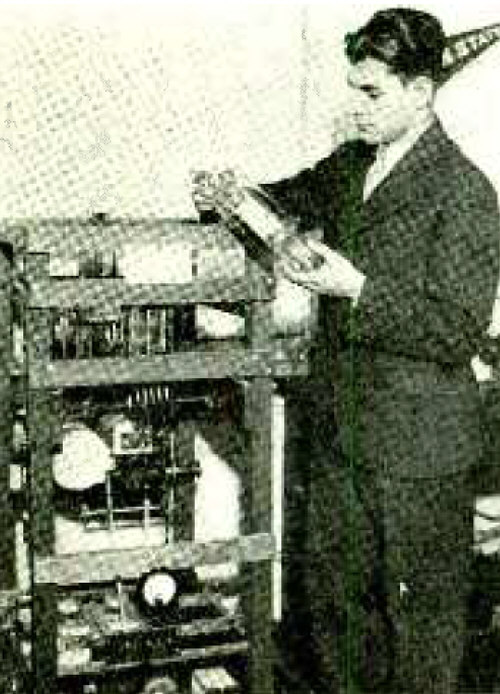
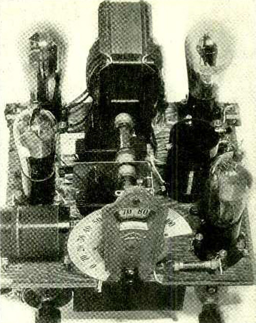
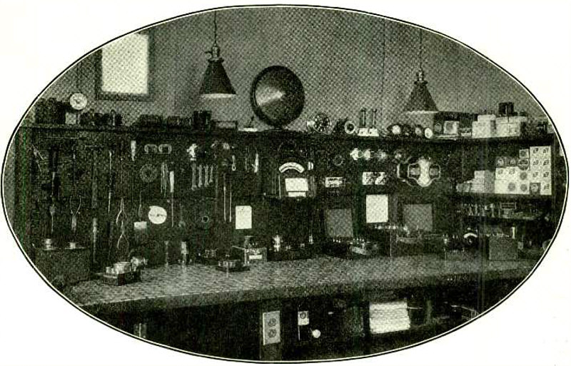
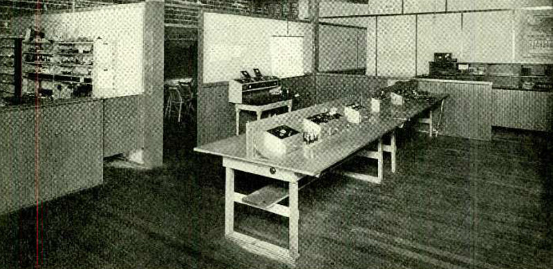
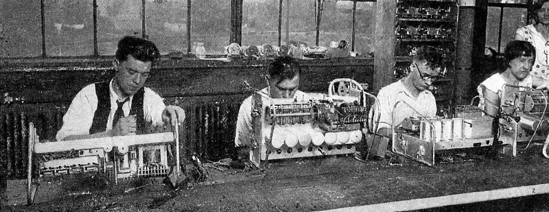
A Well- Equipped Radio Service Shop.
Article: Increase Your Sho p Business and Prestige with an Adequate Test Board - Whose Design and Inexpensive Construction Is Here Described.
"Test equipment in the radio shop, in contrast to the portable kit carried by the service man, should be complete enough to perform any test that a dealer may be required to make. Nor should it be regarded merely as a supplement to the portable kit, which is likely to be out on call at crucial times. An independent test board for shop use may be built at minimum expense and with minimum duplication of equipment by recalibrating inexpensive meters as multi -range instruments..."
(Radio for September, 1929)
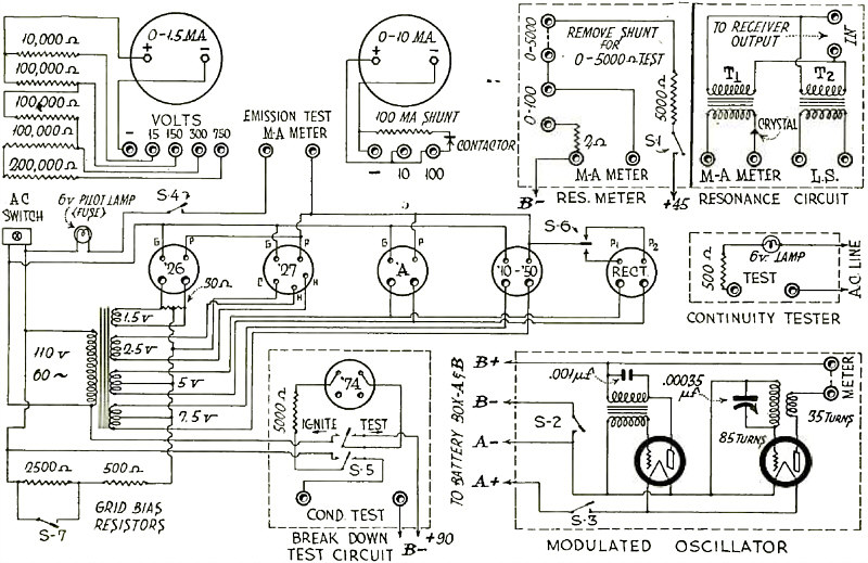
Circuit Diagram of Test Panel.
Article: Increase Your Sho p Business and Prestige with an Adequate Test Board - Whose Design and Inexpensive Construction Is Here Described.
(Radio for September, 1929)
Upper Baseboard Arrangement of Completed Receiver.
Article: An Experimental Set for Local Reception.
"Constructional details for the best inexpensive receiver you ever tried. Uses a -c screen -grid tubes in r -f and power detector stages, and '45 tube in audio stage."
(Radio for September, 1929)
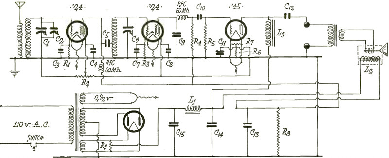
Circuit Diagram of Experimental Three -Tube Set.
Article: An Experimental Set for Local Reception.
(Radio for September, 1929)
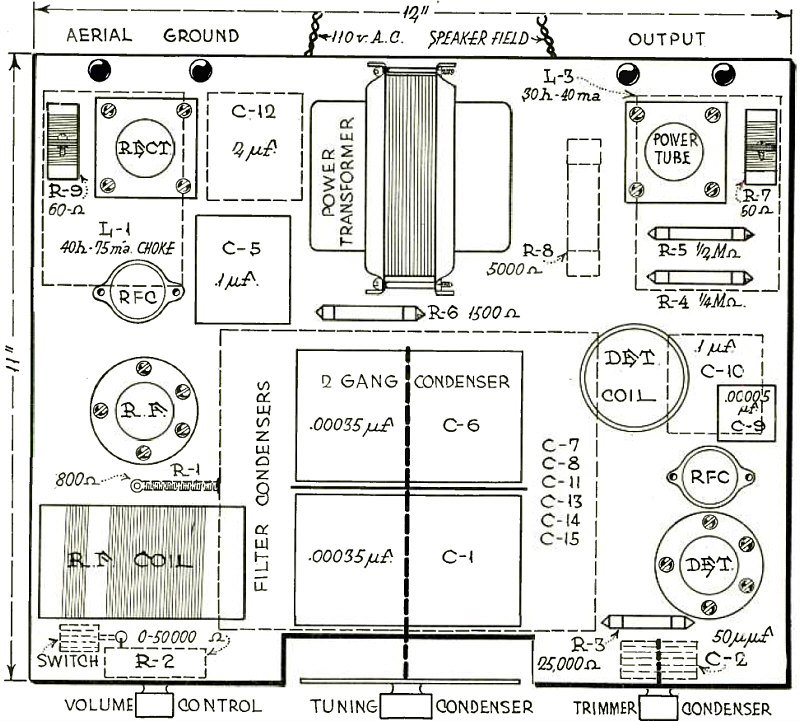
Baseboard Layout of Experimental Three -Tube Set.
Article: An Experimental Set for Local Reception.
(Radio for September, 1929)
Lower Baseboard arrangement.
Article: An Experimental Set for Local Reception.
(Radio for September, 1929)
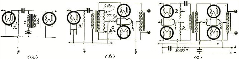
Circuit Diagram of Humless Push -Pull Amplifier With Minimized Filter.
Article: Why Use Push -Pull Audio Amplification.
"A push-pull amplifier stage requires one more tube and socket than is required by a single power stage. For the same operating voltage, the allowable power output is increased by a factor that is closer to three than to two. The filtering necessary to reduce hum to an unobjectionable level is tremendously reduced. This item, particularly in the case of high -power, high -voltage amplifiers, gives rise to a considerable economic saving. A lower voltage power transformer is then satisfactory, since the reduction in filter minimizes the internal voltage drop. The usual audio -frequency filtering required for proper cascade operation of the ordinary amplifier is made unnecessary. And finally, an actual increase in the overall gain of the push -pull over that of the single stage amplifier is realized..."
(Radio for September, 1929)
Interstage Transformers in Low- Frequency Resonant Connections.
Article: Why Use Push -Pull Audio Amplification.
(Radio for September, 1929)
LINCOLN - THE GREATEST ENGINEERED SCREEN GRID SUPER IN RADIO HISTORY.
Advertisement.
(Radio for September, 1929)
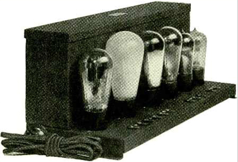
A -F Component and Power Unit of Remler No. 111 Kit.
Article: Kit Reviews - REMLER SCREEN -GRID KIT NO. 111.
(Radio for September, 1929)
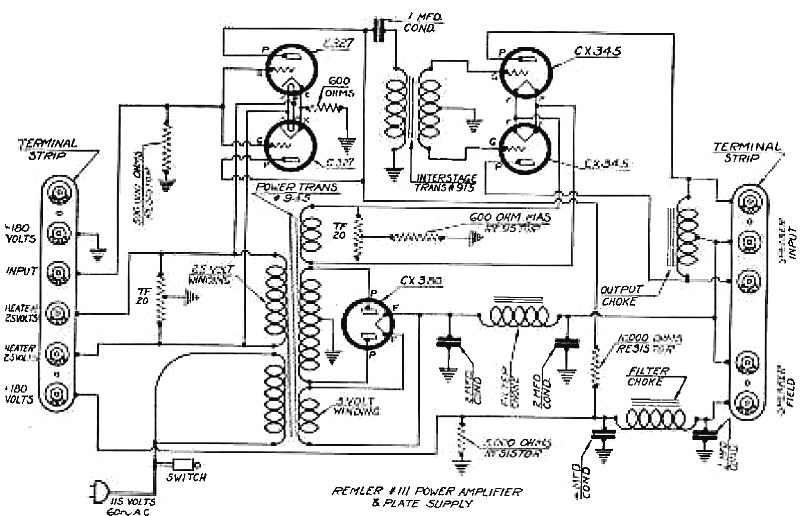
Schematic diagram - Remler.
Article: Kit Reviews - REMLER SCREEN -GRID KIT NO. 111.
(Radio for September, 1929)
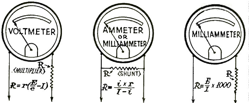
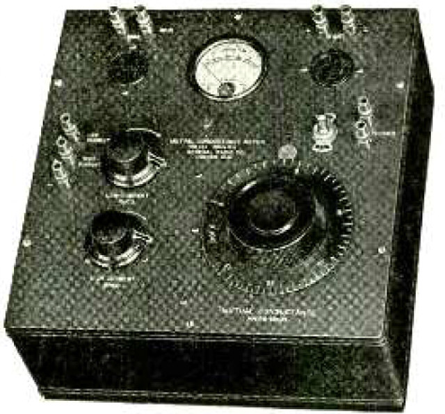
Multiplying Usefulness of a Single Meter ny Mrans of Resistors.
(Radio for September, 1929)
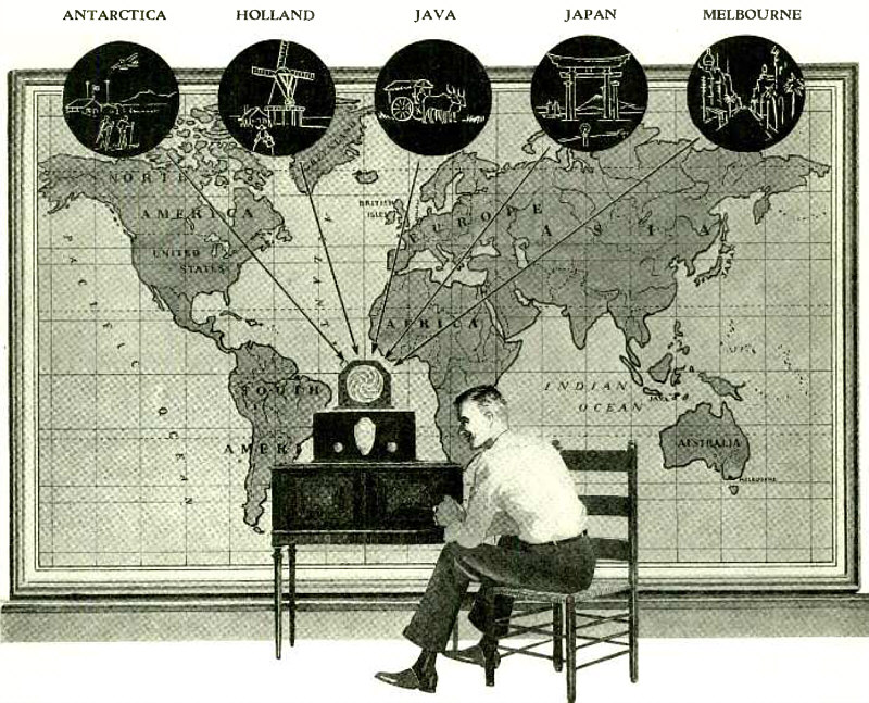
All Around the World!
Advertisement.
"You can hear words and music from Java, Australia. England, France, -from all around the world, -with the NATIONAL Screen -Grid SW -4 THRILL BOX."
(Radio for September, 1929)
MANUFACTURERS' LABORATORY SERVICE.
(Radio for September, 1929)
MANUFACTURERS' LABORATORY SERVICE
(Radio for September, 1929)
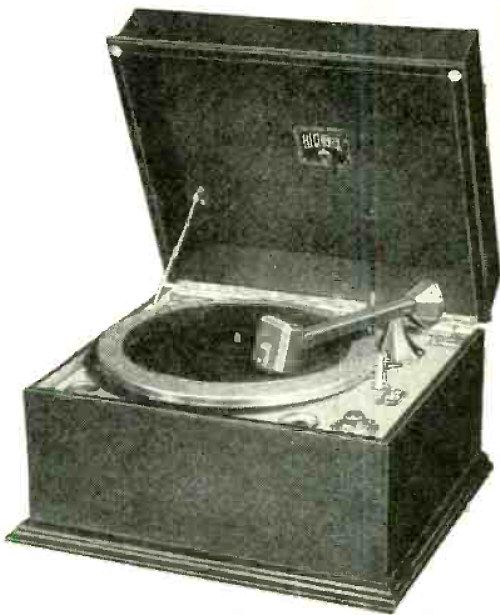
Leutz "Seven Seas" Radio Phonograph Combination.
(Radio for September, 1929)
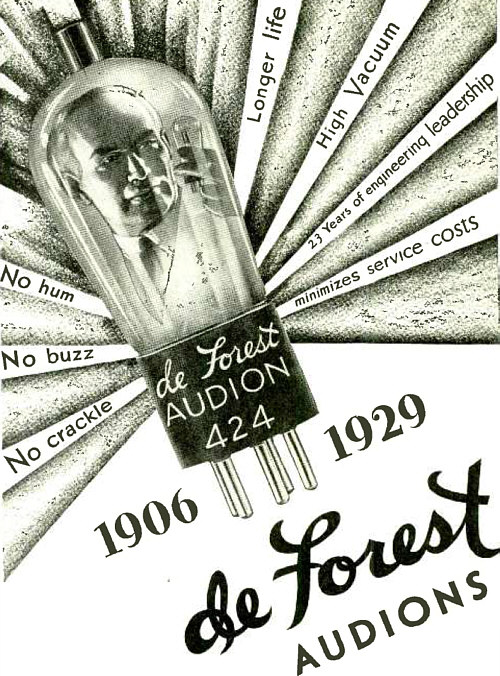
Advertisement.
"DE FOREST Audions have set the world's standard for 23 years. Every other radio tube in the country, no matter what its name, is made under the inventions and basic patents of Dr. Lee De Forest. All the recent improvements of De Forest Engineers are included in De Forest Audions. For example, consider vacuum which determines the life of a tube and its tone qualities. De Forest Audions contain less than 1 -15th the air pressure of most other radio tubes."
(Radio for September, 1929)
Advertisement.
(Radio for October, 1929)
A Convenient Shop Bench with Test Board.
Article: Winning the Customer by Efficient Service Methods.
(Radio for October, 1929)
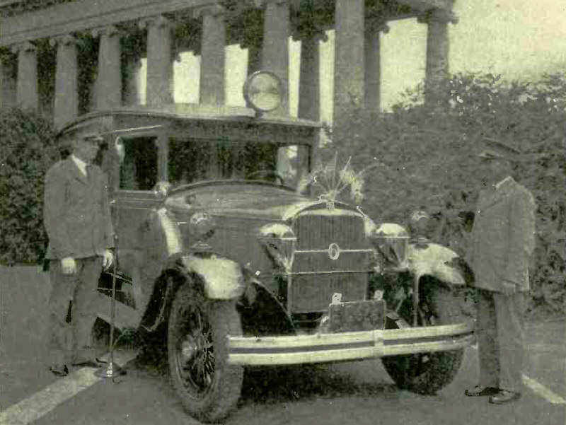
Automobile Which Carries Complete Public Address Equipment.
Articlke: A Mobile Public Address Plant.
"How an enterprising radio jobber is capitalizing public interest in a novel application of radio equipment."
(Radio for October, 1929)
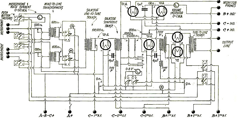
Circuit Diagram of Mixer and Amplifier Unit.
Articlke: A Mobile Public Address Plant.
(Radio for October, 1929)
Side View of Receiving Equipment for Experiments with Television in Natural Colors.
Article: Television in Natural Colors.
(Radio for October, 1929)
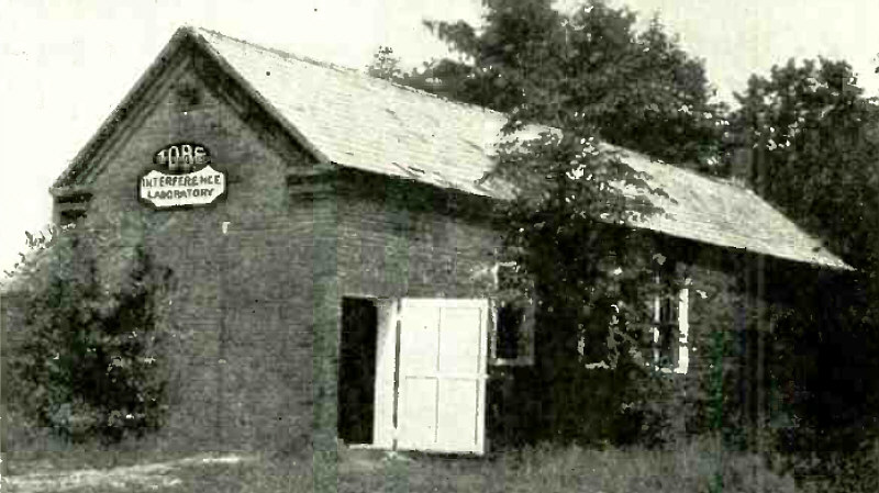
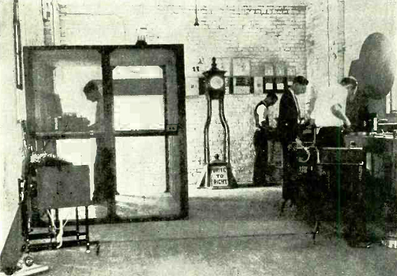
Where Filterettes are Made.
Article: Small Motor Interference - Radio Interference Created by Fractional Horse Power A -C and D -C Motors.
(Radio for October, 1929)
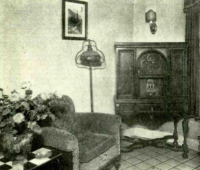
Does your radio set stand the "visitor test"?
Advertisement.
(Radio for October, 1929)
Testing Room of East Bay Radio Service Co.
Articlke: Divorcing Service from Saes.
"Servicing is still a necessary evil in the sale of radio. Even the most highly perfected a -c set is liable to develop some little trouble which calls for the attention of a service man. Anticipating such trouble, the dealer generally gives free service for a limited time after purchase and installation. Thereby he insures satisfaction to the customer."
(Radio for Novermber, 1929)
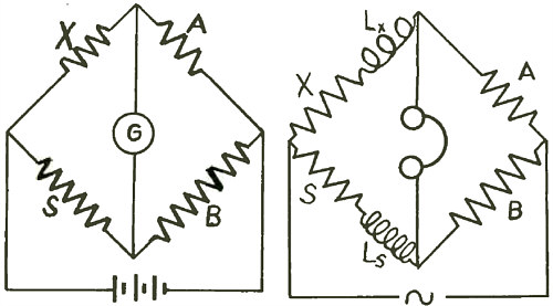
Circuit of Simple Resistance Bridge (Left), circuit of Simple Inductance Bridge (Right)
Article: Let's Play Bridge.
"Those who go in for filters and equalizers and general test work need a bridge to measure inductance and capacity to within 5 or 10 percent. After the theory of its operation is understood any service man can readily make such a bridge at low cost..."
(Radio for Novermber, 1929)
The Bridge Itself (Left). The Innards of the Bridge (Right)
Article: Let's Play Bridge.
(Radio for Novermber, 1929)
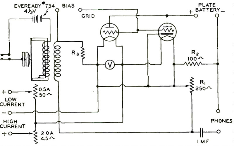
Diagram of Tube Checker.
(Radio for Novermber, 1929)
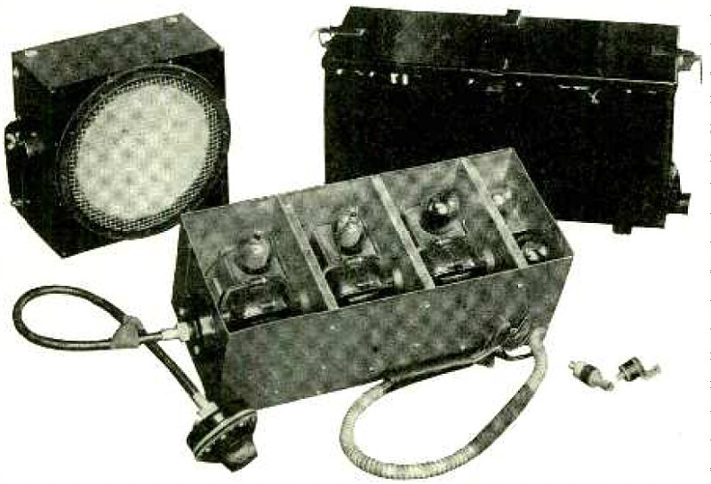
Tube Checker.
(Radio for Novermber, 1929)
Circuit Diagram of Mutual Conductance Meter.
(Radio for Novermber, 1929)
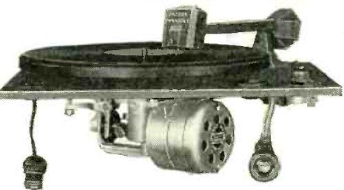
The Delco -Remy Automobile Receiver; Tuning Unit With Lid Off, Loudspeaker and Battery Box. Notice the Two Small Resistors for Shunting Spark Plugs and Coil.
(Radio for Novermber, 1929)
Advertisement.
(Radio for Novermber, 1929)
Advertisement.
(Radio for Novermber, 1929)
Advertisement.
(Radio for Decermber, 1929)
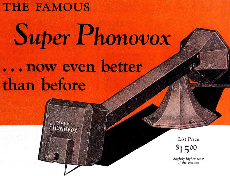
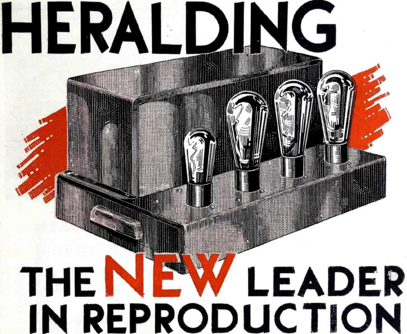
Advertisement.
(Radio for Decermber, 1929)
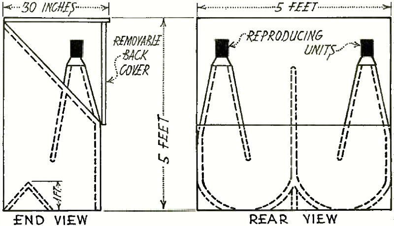
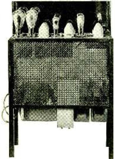
Power Amplifier Installation at El Cortez Hotel.
Article: Profit from Public Address Installations.
"Money -making hints for the live dealer and service man in applying standard amplifiers and reproducers to local situations."
(Radio for Decermber, 1929)
The "chassis cage," employed at the Gulbransen factory to protect projecting parts of the chassis from strain, suggests itself as a handy addition to the radio service shop. It would have to be somewhat adjustablein order to accommodate all types of chasses but this is a matter that could be solved by the mechanically inclined service man.
Article: Profit from Public Address Installations.
(Radio for Decermber, 1929)
Transmitting Equipment Used in Farnsworth System of Electrical Scanning.
Articlke: Transmission of Television Images.
(Radio for Decermber, 1929)
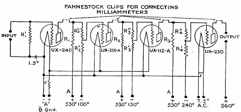
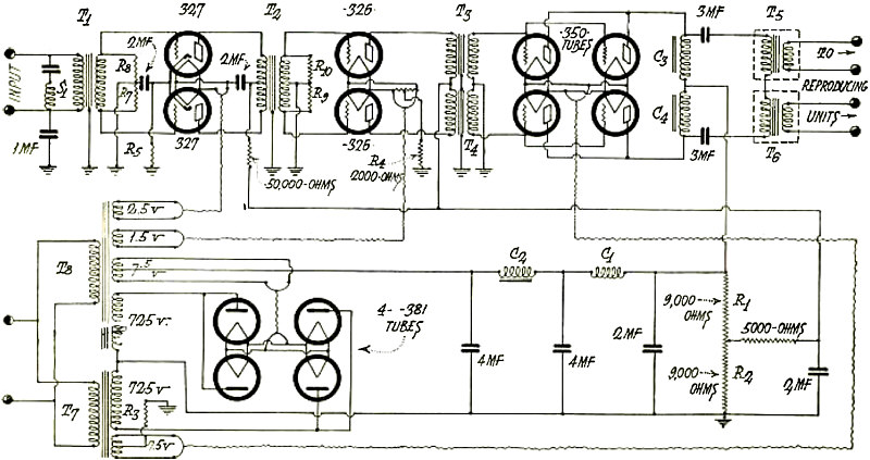
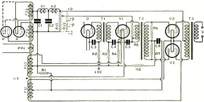
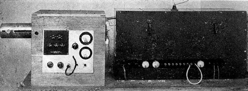
Resistance -Coupled Amplifier Circuit.
Article: A New Resistance -Coupled Amplifier.
"A four stage resistance -coupled audio amplifier which is designed to give a gain of 55 decibels and an undistorted power output of 4/ watts over a 30 -10,000 -cycle band has been designed by the engineering department of the International Resistance Co. Together with its associated 800 -volt power supply it may be used as a phonograph pick-up, a power amplifier for an r -f and detector unit, or for laboratory measurements of loudspeaker fidelity."
(Radio for Decermber, 1929)
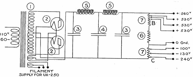
Circuit Diagram of Power Supply Unit.
Article: A New Resistance -Coupled Amplifier.
(Radio for Decermber, 1929)
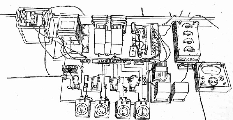
General Layout of Parts in Amplifier and Power Units.
Article: A New Resistance -Coupled Amplifier.
(Radio for Decermber, 1929)
Time Switch for Street Signals, with Filterette.
Article: NEW UNIVERSAL FILTERETTE FOR SIGN FLASHERS
(Radio for Decermber, 1929)
[Previous period] [Next period]
")
")
")
")
")