 Tube amplifier "Mikrus PCL86"
Grzegorz "gsmok" Makarewicz,
PCL86 electron tube belongs to a group called "TV tubes" - tubes used in TV sets produced in the last tube TV's. In general, the models produced in the late 70's and early 80's of last century were already mixed transistor-tube devices. A classic example of this TV was the "Libra" produced in the Warsaw Television Plant (WZT). With this design sentimental memories bind me, because I belonged to a group called. "assemblers" who, as the name suggests, were involved in assembling these TV's from parts obtained from "Bomis" (younger Internet users have a little search online to find out what it was).
All the local neighbors and my immediate family members were equipped with the "Libra" brand TVs assembled by me. They were happy to have devices that were deficient in those days, and I had a financial support to my student's budget. With some embarrassment I have to admit that television tubes used in "Libra" TV's were for me, at that time, a necessary evil, with which I had to accept being dependent on the WZT constructors ideas. Just like other assemblers, I immediately resigned from the "compulsion" living with them, if only on the horizon (read the Bomis offer) appeared fully transistorized TV sets like "Vela", "Telefunken" etc.
PCL86 tubes have a real bad luck when it comes to their appreciation by manufacturers of audio equipment. The main reason of this misfortune were ECL86 tubes - with similar characteristics, but adapted to the filament voltage of 6.3V. They were for many years the fundamental tubes used in small low-frequency amplifiers. Their "TV counterpart" - PCL86 tube was treated simply as a second-class tube not suitable to be used in audio amplifiers.
Recently, after many years of "humiliation" the PCL86 tubes begin to be noticed by tube sound enthusiasts. What is the cause? Could it be revealed to their mysterious sonic characteristics? Nothing like that. Just ECL86 stocks were virtually exhausted, their prices rised to exorbitant levels and designers had to accept PCL86 tubes as audio tubes.
In literature and publicly available online resources you can find many low-frequency amplifier schemes based on the PCL86 (ECL86) tubes. Amplifier described here (in two versions) is based on the classic, recommended by the tube manufacturers configuration shown in Figure 1. The diagram shows only one (right - R) channel of the amplifier, the second channel is of course identical. The elements of the left channel are marked with the letter "L" (for example, C4L, R4L), elements of the right channel are marked with the letter R (eg C4R, R4R), and elements common to both channels don't have additional markings (eg, C13, R13, LED1).
Additionally, in Figure 1 I took into account all the elements that make it possible to build an amplifier in the version published in "Elektronika Praktyczna" magazine (2/2005). To assemble the amplifier in a form identical to the published in "Elektronika Praktyczna" magazine resistors R8L, R8R, R9L, R9R, R10L, R10R, R13, capacitors C10L and C10R and LED1 have to be omitted. Additionally screens of PCL86 tubes have to be connected directly to the HT supply (Ua).
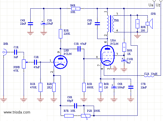
Fig. 1
Figure 2 shows a schematic diagram of the power supply of the amplifier comprising the filament supply and two anode voltage power supplies for both channels.
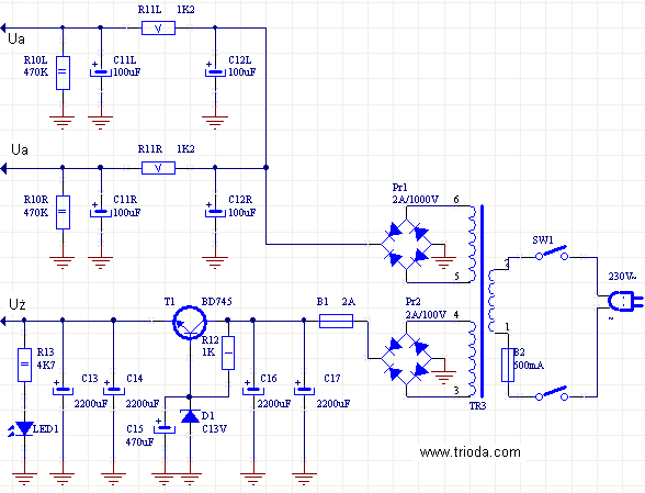
Fig. 2
I assembled the amplifier in two versions, which differ in mechanical construction. Both models are shown in Figure 3.
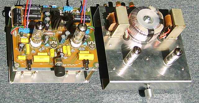
Fig. 3
On the left side the amplifier in the form of a "tower"is shown. On the right there is the amplifier assembled in the traditional form of a small aluminum chassis.
The amplifier version 1
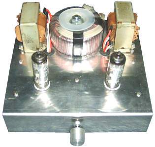
View of the amplifier in the form of the tower is shown in Figure 4.
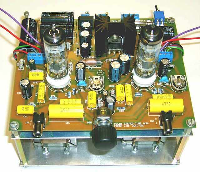
Fig. 4
For the first amplifier I designed a single printed circuit board shown in Figure 5. As you can see is a one side printed board which does not require any additional jumpers.
Fig. 5
Figure 6 shows the outline of the components of the amplifier.
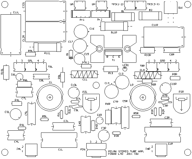
Fig. 6
The PCB was designed in such a way that can be mounted on it, not only electronic components but also all the additional elements, including input jacks, potentiometer for volume control and power switch. Please pay special attention to the use of appropriate jack sockets so the input and ground signals were connected to the appropriate pads on the PCB. If necessary, correct the entry path on the PCB.
Installation of additional components is of course optional. In the case of housing, which does not allow for the insertion of the board with these elements, the jack, potentiometer and a switch can be mounted on the housing and connected to the board by wire. View of the printed circuit board mounted with components is shown in Figure 7.
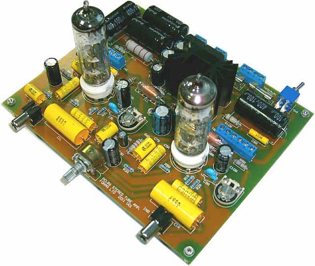
Fig. 7
On the printed circuit board descriptions with indications of elements are located. They are consistent with the indications in the schematic diagram. Before soldering the element is worth to make sure it was installed in the right place - thus avoiding the need of desoldering - which is not a pleasure.
The best practical assembling method is to start soldering from the smallest elements (resistors R1L, R1r, R2L, R2R, R3L, R3R, R5L, R5R, R7L and R7R). Next, assemble the parts that are slightly higher (R4L, R4R, R8L, R8R, R12, R9L, R9R, R13, D1, R6L, R6R, R10L, R10R, C8L, C8R, B1, B2, CLL, CLR) etc.
From my experience, the ARK connections have a negative feature, which consists in the fact that some of the leads can cause cold solder, so you should pay special attention to the effect of solder and it is advisable to degrease them and not touch before soldering.
R11L and R11R resistors heat up much during the operation of the amplifier. Thei should be soldered in such a way as not to touch the circuit board. It should be noted that the resistor R11L should be positioned as far as possible from the electrolytic capacitor C12R. If this resistor is mounted on long legs over the plate it is possible that the element is bent and accidentally makes contact with the C12R capacitor case - this is unacceptable. This resistor should be the most bend of the capacitor. If it is possible install this resistor on the solder layer of the printed circuit board.
Radiators are often fitted of rivets used to attach them to the PCB. To mount the radiator in the "traditional" way rivets should be removed and the radiator can be screwed. Please note that the screws do not touch its head against the tracks - this can happen when using screws that are too large. In any case I recommend the use of screws with insulating washers.
RCA input sockets when connecting and disconnecting cables are subjected to high stresses. Therefore, the holes in the circuit board I designed in such a way that the connecting/disconnetcing cable does not cause damage (breaking) pathways, which are soldered to sockets. Each slot in addition to the signal output terminal has two tabs which are additional mechanical reinforcement. These tabs have a square cross section, and the diameters of the holes in the PCB are such that you need to use considerable pressure force to the socket to properly lock it on the PCB. If you have trouble inserting the socket, you can use a slightly rounded tabs. Keep in mind that the more rounded tabs, the easier it is to press the slot, but the lower is their mechanical stability.
The following figures show the construction details of the amplifier assembled in the form of a "tower".
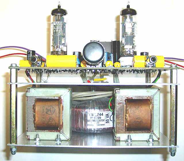
Fig. 8
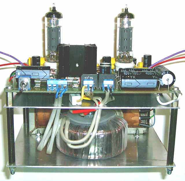
Fig. 9
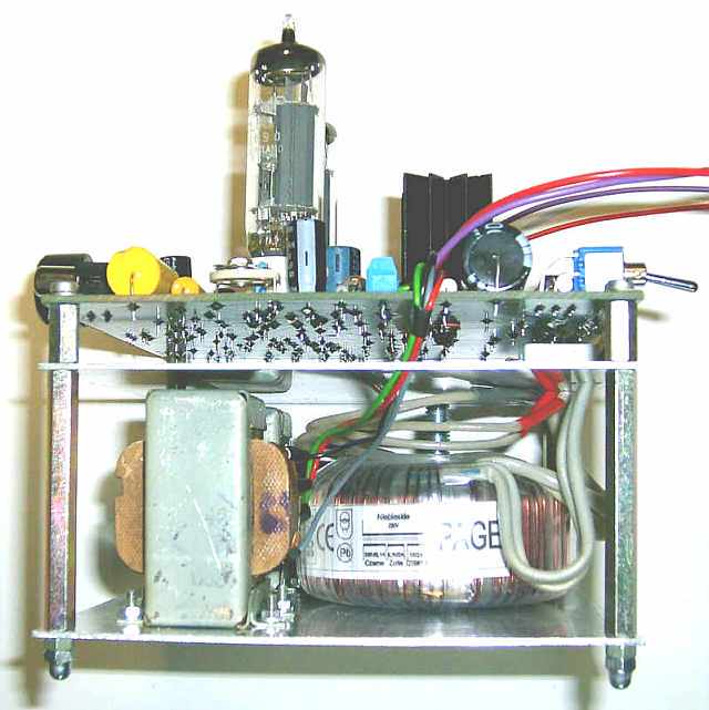
Fig. 10
The amplifier version 2
View of the amplifier assembled on an aluminum chassis is shown in Figure 11.
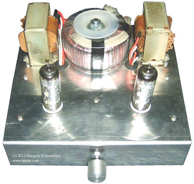
Fig. 11
The schematic diagram has been slightly changed compared to the first version. Diagram of the amplifier is shown in Figure 12.
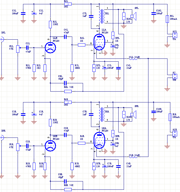
Fig. 12
The diagram od the voltage supply is shown in Figure 13.
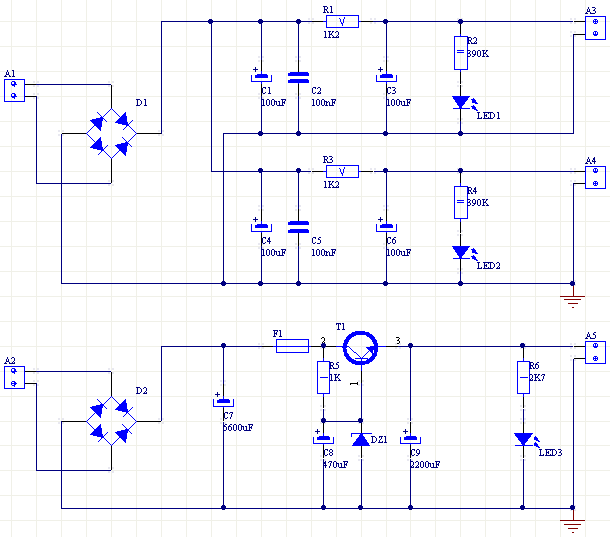
Fig. 13
Amplifier components are mounted on two printed circuit boards - amplifier and voltage supply separately. In Figure 14 and Figure 15 the amplifier and it's electronic components are presented.
Fig. 14
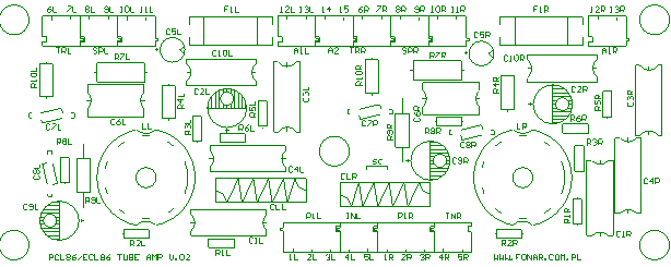
Fig. 15
In Figure 16 and Figure 17 the voltage supply and it's electronic components are presented.
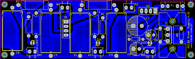
Fig. 16
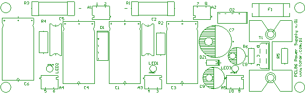
Fig. 17
Figure 18 shows the photo of partially assembled board containing a section of the amplifier. There is currently lack of unmounted ARK connectors. As you can see the tube sockets and the same tubes are placed on the copper side of the printed board.
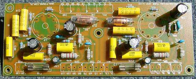
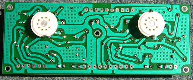
Fig. 18
Figure 19 shows the supply section of the power amplifier. All of the components are soldered except for the transistor and heat sink.
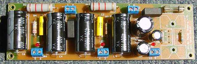
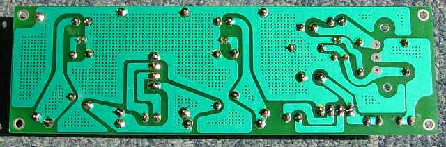
Fig. 19
The following figures show details of the assembled amplifier.
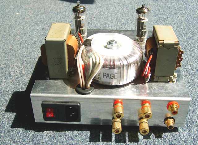
Fig. 20
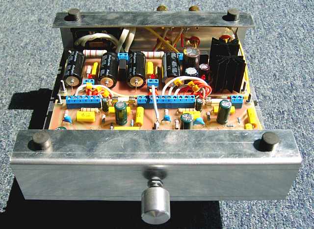
Fig. 21
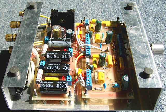
Fig. 22
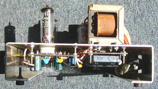
Fig. 23
Grzegorz Makarewicz with the permission of FonAr Ltd.