Piotr Mason (HAIKU-AUDIO)
Tube amplifier named "Auris" was produced by Audio-Akustyka. According to the specification, it can work as a pentode or triode amplifier, in Push-pull or Single-ended mode, with or without a negative feedback, and in the mysterious "turbo" mode. The manufacturer does not allow peering into the housing due to the use of many "non-standard proprietary solutions". Time to break the seals and keep one's ear to the ground.
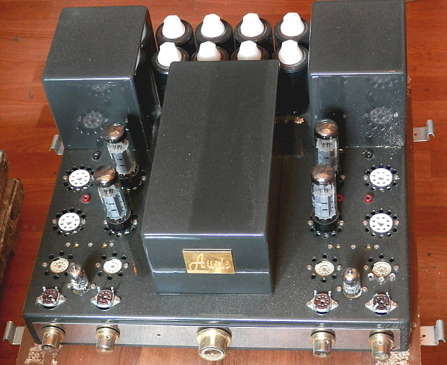
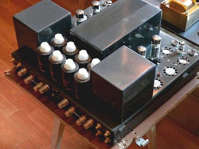
About two weeks ago, the amplifier came to me with a diagnosis of "playing badly, sharply and with no bass" and the recommendation of elimination of mentioned sonic defects with simple means. The amplifier was packed in a box from chipboard. On the whole parcel weighed 48kg. Once opened, I found the following view:
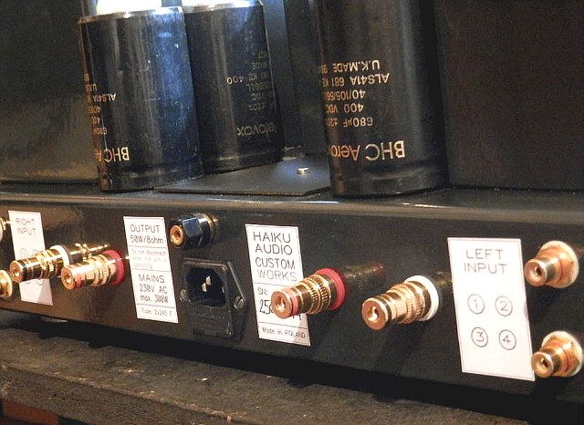
According to information received from the owner, the amplifier has been modified by the manufacturer so as to operate all the time in a triode SE mode with the ability to use one to four power tubes of any type. Despite the presence of five 9-pin (noval) tube sockets on each side, the only control tubes were ECC88 - one per channel. Intriguingly, the amplifier has two secondary windings brought out to four separate terminals which, according to the manufacturer's instructions were to be connected in series to 8Ω load and parallel to 4Ω load. Of course, replacing the winding connection from the serial to parallel we have the voltage change ratio 1:2, and hence the resistance ratio 1:4.So it would be more appropriate to describe the loads as 16Ω and 4Ω or 8Ω and 2Ω.
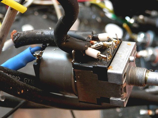
Central knob is the power switch (about this later),while the other four are: input switch and volume control, separate for each channel. Potentiometers are equipped with motors and controlled by remote pilot. The balance is realized in such a way that only one of the potentiometers is rotated, destroying the volume symmetrization (some sort of one channel volume offset), then the volume control rotates both potentiometers simultaneously. It's easy to guess that getting a synchronous volume control in this way is basically impossible.
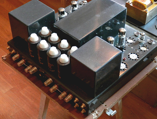
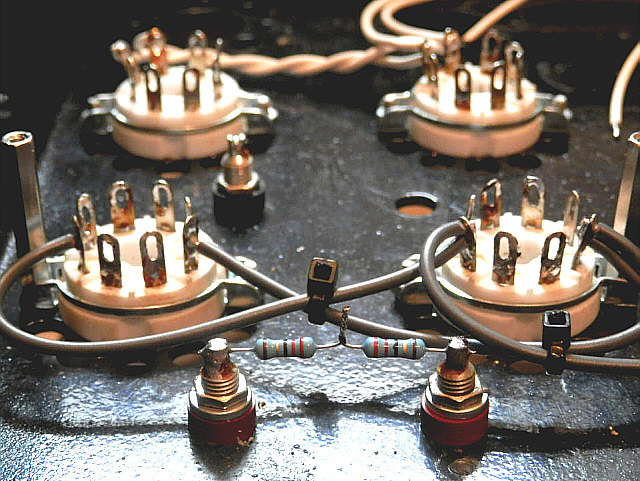
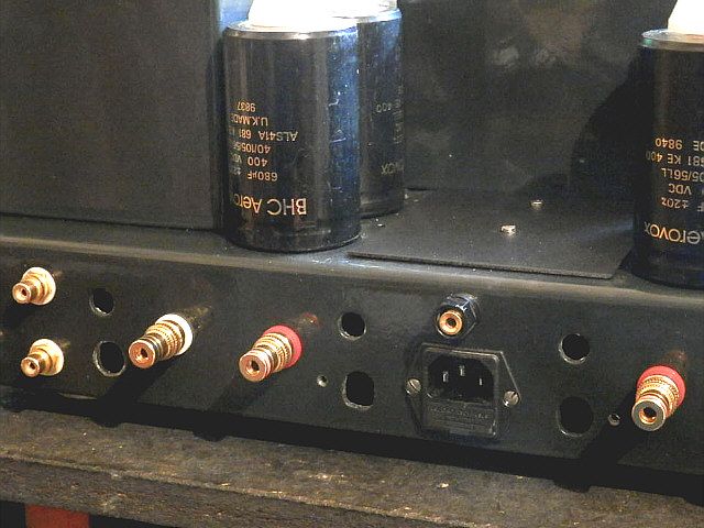
On the back there are two fuse holders, one for each pair of tubes. Banana plugs between the tubes serve as measuring points for adjusting the quiescent currents (biasing) of each pair. To make the adjustment, a milliammeter should have been connected to appropriate slots with simultaneous removal of the fuse assigned to the biased tubes so enabling the current flow through the meter.
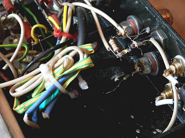
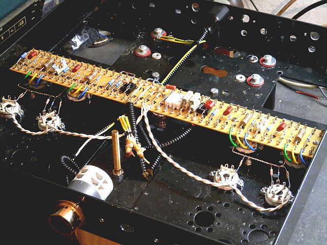
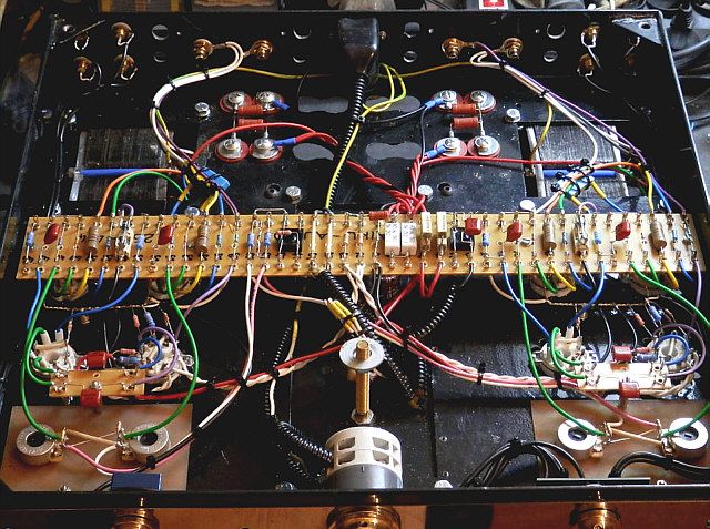
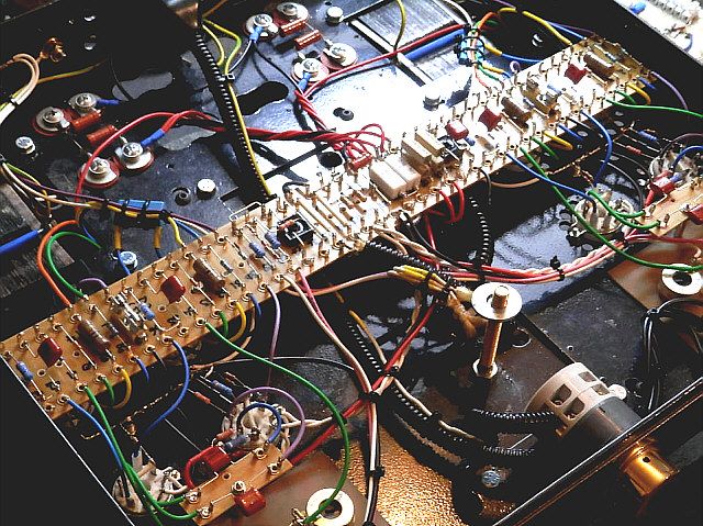
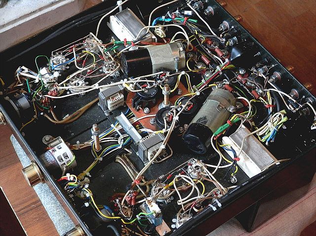
It is time to turn the amplifier upside down. I had to wait for help, because as I mentioned, it weighs 48kg. After reversing amplifier and loosening the spikes, which serve both as lower legs and mounting bottom cover elements, I saw the following picture:
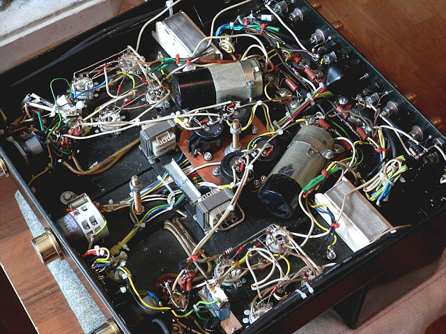
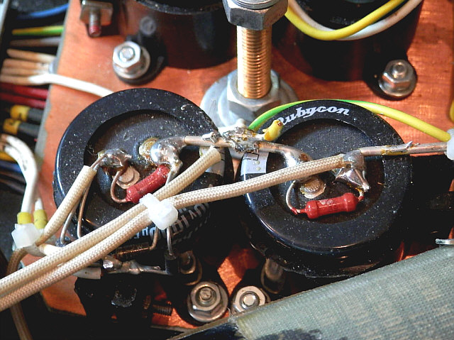
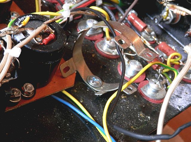
The two largest capacitors are 2200uF/420V. As it turned out, supply voltage was 430V at nominal 230V supply and all the stages of the amplifier connected (full load). White cubes in the vicinity of these capacitors are chokes from tubular fluorescent lamps.At no point of the amplifier I found anything like the rail or single point grounding. The individual elements are connected by loose wires of various cross-sections and colors of the insulation on each of the channels in another way. Along the sides of the chassis there are thick "Klotz" cables connecting inputs with switches. The metal bracket in the center of the amplifier presses the wiring bundle to the chassis. Isolation of power transformer pins is melted and left a very difficult to remove colored spots. As a result of the modification, part of the transformer windings become redundant. They were left in the form of long, sloppily tied cables. The feedback has been removed, or more specifically brutally severed. Output terminals are "equipped" with useless hanging resistors. The chassis is densely sprinkled with rosin and tin droplets embedded in the paint.
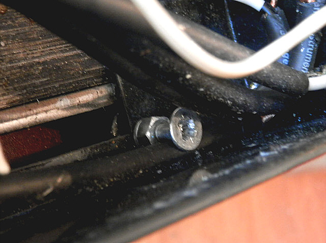
Output terminals are connected to the transformer using the same cable as used in input terminals/switch connections (thick shielded wire made by Klotz). Terminals as such, are fixed with strange heavy bolts and wires soldered directly to the outlets, without the use of solder eyelets. The insulation is burnt in many places due to improper use of soldering iron.
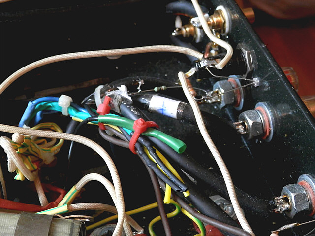
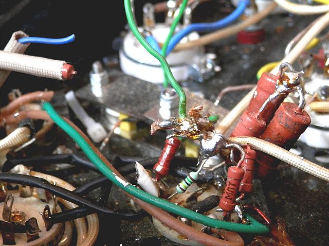
In the initial stages of MŁT resistors are used. Soldering was performed in a rather chaotic manner with the use of large amounts of tin. The relay used probably to switch working modes and redundant after the modification, hangs on the "quick connector" with the remains of cut wires.
In the second channel relay is completely different. It is screwed through plastic cover which loosened and inside of the relay fell out of it's housing.
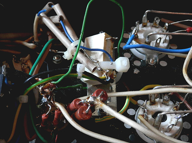
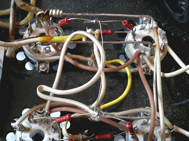
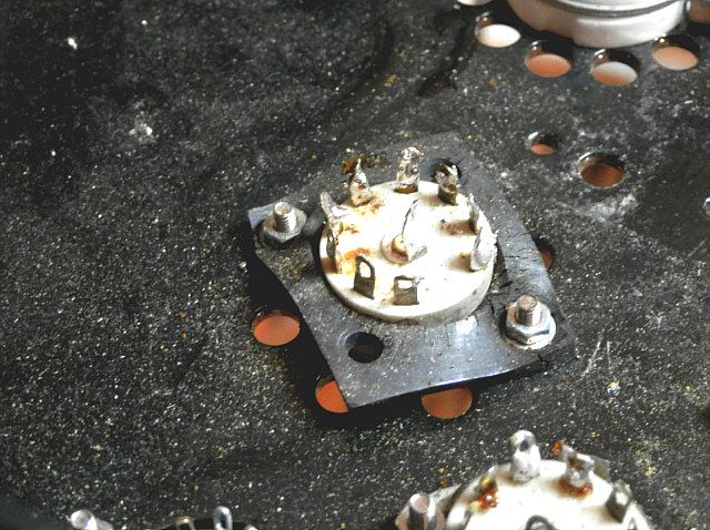
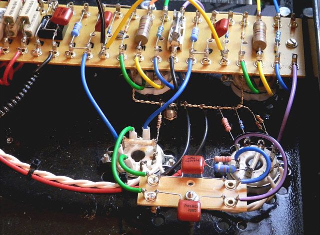
Heating volteges are applied do the sockets be means of thick, uninsulated silver-plated wires for power tubes and thin insulated silver-plated wires for all remaining tubes. The wires are not twisted with each other, or even stacked in any planned way. Grid resistors cere soldered to each other without wrapping or using any pins protection. Connections between the socket pins are made with rolled back and forth wires two to three times longer than necessary.
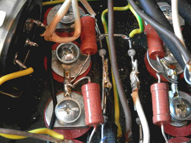
Negative voltage power supply contains 4x1000uF/200V capacitors, with capacity sufficient to supply the average optput power stage. Capacitors are mounted on a piece of laminate with copper layer which is not connected to anything. Diodes and resistors are soldered so short that their cases are molten with soldering tin. Here also you can see the cut of wires left after modification.
In the negative voltage section two small power transformers (230V-12V) of series connected windings and cores without gaps play a role of chokes.
Rectifier diodes in anode power supply are located about a millimeter from surface of the chassis and connected to the anode wires of the mains transformer without wrapping or using any protection.
Interestingly, in the rewiev [Audio-Akustyka Auris - recenzja w High Fidelity] the reviews editor noted that "chokes, looking like chokes for fluorescent lamps" but this remark does not induce any negative reaction, like burnt wire insulation, which can be seen in the pictures of the interior.
Taking into account the implementation details of the amplifier presented above, I decided that the only way to repair it is ... build it from scratch; I emphasise - completely from scratch. I assumed at that output and power transformers are good enough to use them in new construction. I could not get to the transformers to verify them without "destroing" the amplifier's construction, and that meant taking on the task of rebuilding without the possibility of returning to its original state. I assumed optimistically that the transformers were good so I stepped into action with the cutters. Thanks to them I could get to the first bolt holding a transformer's can and remove it using the Phillips screwdriver. The second required the use of a flathead screwdriver while the last two require a 10mm socket wrench. As you can see it was a fairly large set of tools.
Transformers were not connected with cans in any way, but merely pressed against with a small wooden wedge.
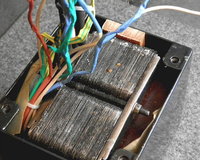
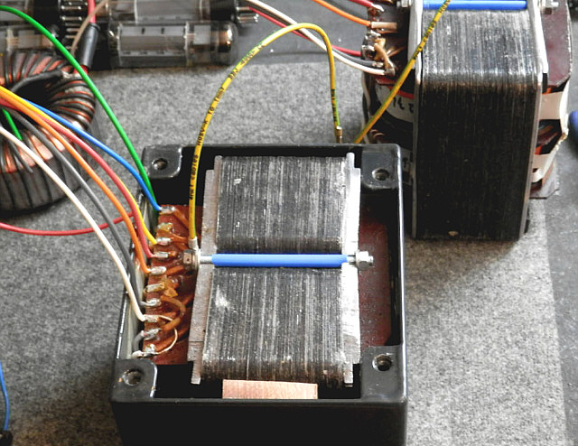
Once removed, viewed and measured it turned out that the transformers are without a gap, so dedicated to be operated only in a push-pull configuration; with four secondary windings (derived out as two separate windings) and six primary (arranged between the two symmetric halves of the bobbins).
With the series connection of primary windings and secondary windings connected in parallel impedance ratio was 3kΩ-8Ω, which resulted in the subsequent selection of the power stage configuration. In addition, transformers have four winding formed from a single layer of fine wire, giving the voltage equal to half the voltage of the secondary winding. Originally, according to information from the description of the press, they were attached somewhere after selection of the enigmatic "turbo" mode. Because of the very small number of turns, I found them to be useless.
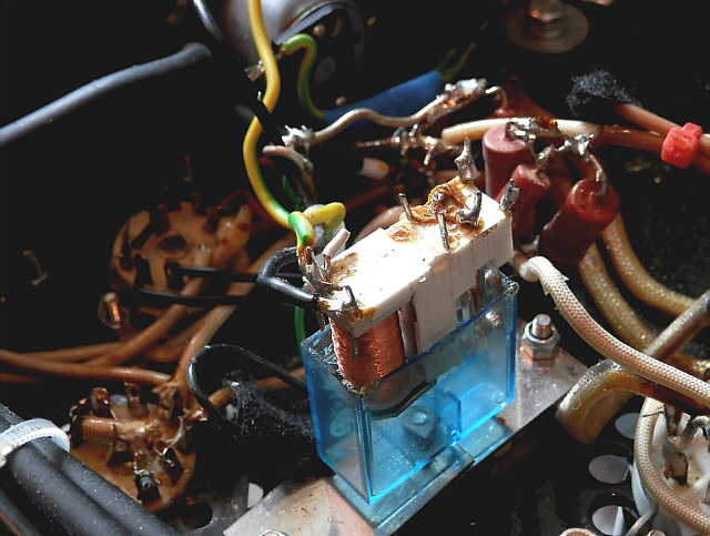
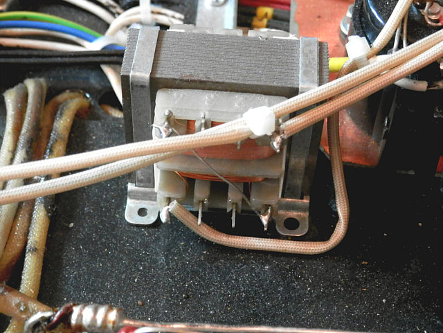
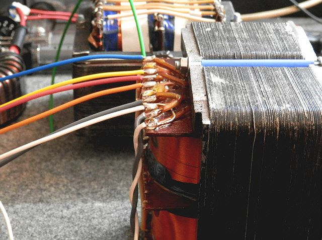
In the picture you can see again a lot of burnt insulation and broken soldering tags. Clamp the core is an element welded from pieces of black steel.
In a system which I got transformer was used in the SE configuration with a full DC current component passing through the primary winding. I have the impression that, in combination with the lack of gap in the core this was the main reason for the "bass problems" indicated by the owner of the amplifier.
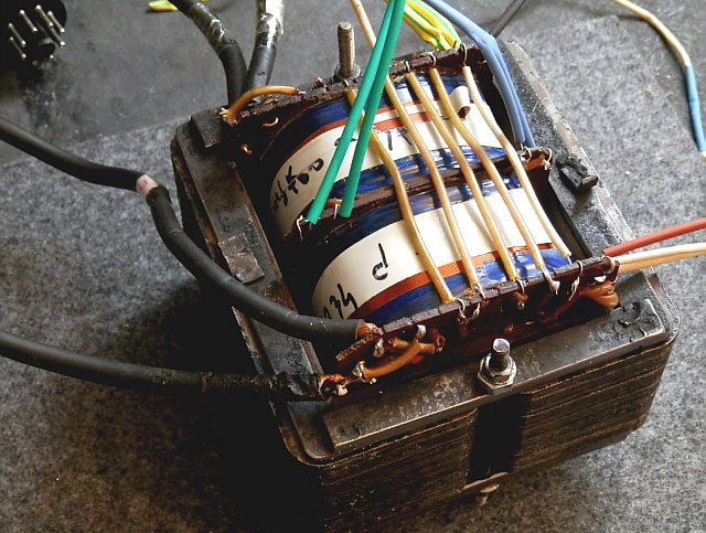
Power transformers are made in the form of two toroids 400W each and secondary windings: 320V/1A, 290V/50mA, 100V/50mA, 12V / 0,6 A, 6V3/7A and 6V3/2A. Attempting to connect of the transformer loaded with tube heaters and filter capacitors, caused the spectacular blow of the fuse and dimming all lights in the building. Also attempting to connect of only one transformer with no load to the mains socket, caused the fuse on the corridor of my workshop to blow. I did't try to turn on two power transformers at the same time.
Interestingly, the amplifier was equipped with a special protective thermistor, but as it turned out, it had a value of only 2.5Ω. Eventually the use of 20Ω thermistor allowed to freely turn on the amplifier without having to turn off the lights, or running back and forth to the fuse box.
After examining transformers I decided to use only one of them and build the system shown in the diagram below. But first I had to deal with all that was fixed to the chassis.
Having decided to rebuild the circuit I decided to remove absolutely all the elements from the chassis and begin construction of a new circuit retaining only the transformers and tube sockets. I started the "demolition" from 2200uF/420V capacitors that were fixed with too small clamps. What is more, they were bent with pliers in order to be used differently than provided for, which meant the capacitors not standing on the chassis, but lying beneath it.
One clip of a clamp was fixed with a screw adapted to a Phillips screwdriver and the other for a flathead screwdriver.
In mentioned review the use of inappropriate clamps wasn't commented, even though the picture shows that they are similarly bent and does not fit.
Volume potentiometers were placed in shrink"sleeves". After cutting it turned out that in each channel there is stereo potentiometer with only one section used. Thick wires were soldered directly to the bent pins provided originally for printed circuit board. Again, a lot of burnt insulation, tin drops and omnipresent rosin layer.
Resistors used in input stages "met in balls of tin". Most of them are old MŁT type.
Metal clamps were removed from noval tube sockets and raplaced by rubber ones. I suspect that was idea to isolate tubes from vibration of the housing. Under the influence of time and temperature rubber become brittle and sockets loosen up. Hole spacing as used did not correspond to the standard noval sockets with metal clamps. This led me to the total abandonment of noval sockets in the framework of amplifier reconstruction. The gray haze visible on the chassis is of course rosin.
You can say that most of the holes in the chassis were made inaccurate. Each element that was mounted was labeled (left/right and front/back), because when you try to replace or it the mounting holes did not match up.
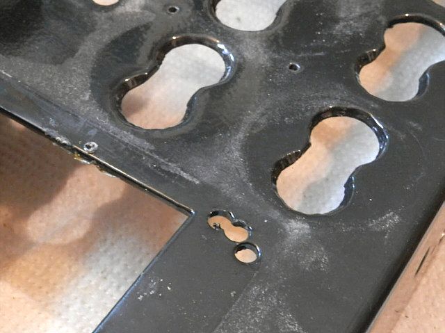
In the end, after a hard day at work I had a bare chassis with nasty curved holes and I could start fitting the new design.
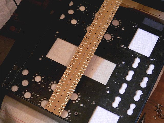
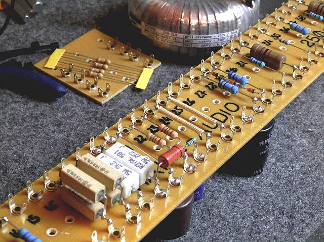
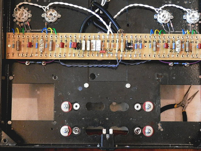
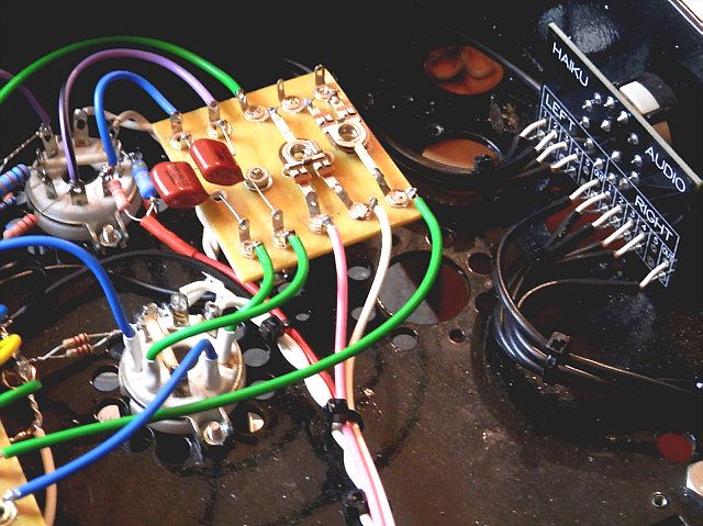
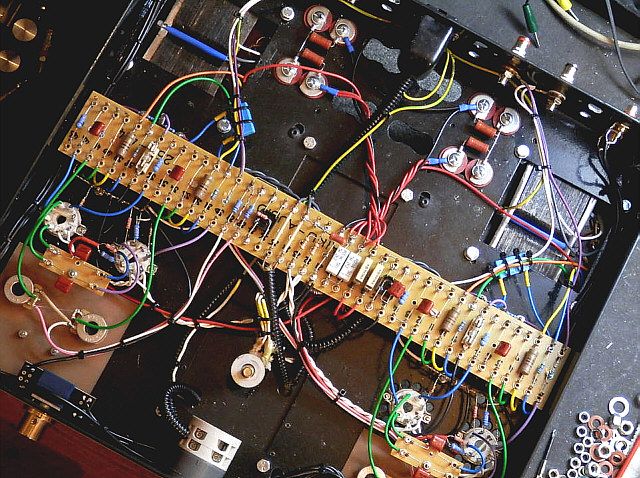
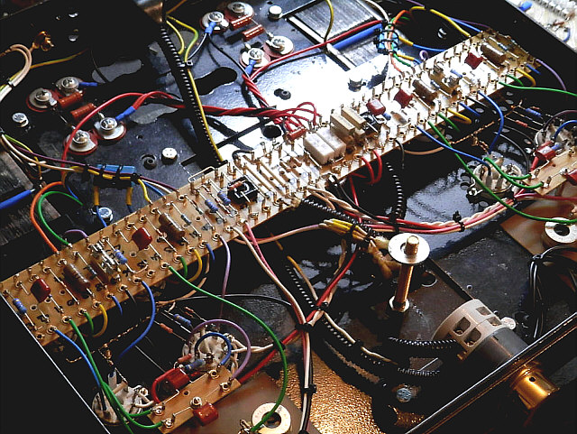
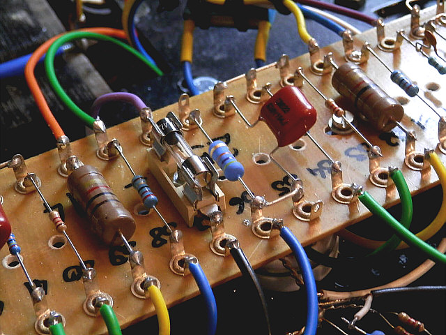
After selection of the circuit configuration, drawind a schematic diagram and clearing the chassis, I started to arrange elements. I decided to put all the little components on a very handy board extending across the amplifier. On the board I was able to mount 47 pairs of soldering tips. Almost as much as needed.
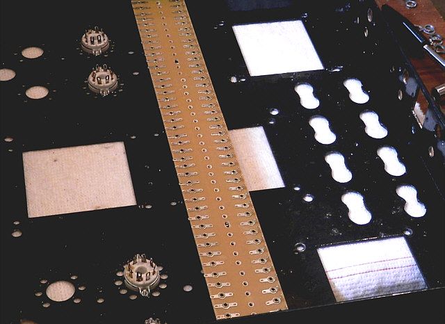
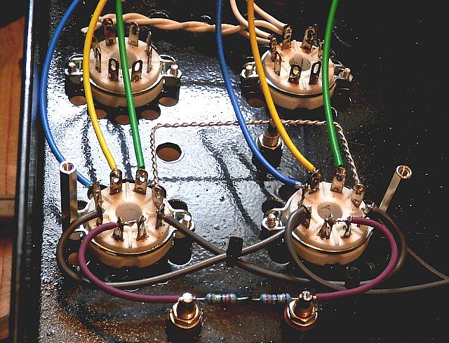
I started by laying tube heatings using twisted wires: separately for power tubes, separately for signal tubes, because power transformer had just two heater windings: 7A and 2A. The first winding remained at ground potential, while the other is balanced and raised about 50V for the comfort of phase inverters. You can also see metal film resistors (1%, not MŁT) for indirect measurement of quiescent currents. As a result, there is no need to remove the fuse when adjusting the amplifier.
Below you can see the color coded cables and a local mass rail. Personally I do not prefer such a solution, but the chassis dictates the placement of the power supply between the channels of the amplifier, so I was forced to use such a configuration.
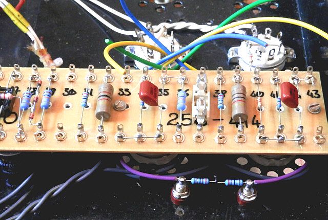
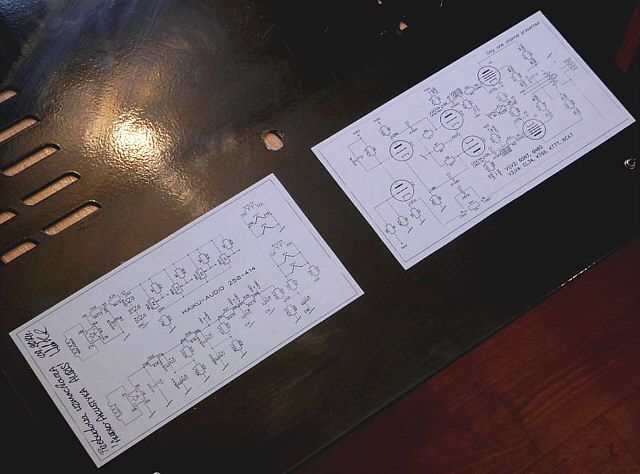
The numbers at the lines on the schematic diagram indicate the position of the point on the mounting plate. In this way you can quickly find appropriate place in the amplifier looking at the diagram.
This time fuses are located in close proximity to the power tubes. In my opinion, if there is a fuse blow, it would be necessary to look inside and see what was the cause, so placong fuse holders on the outside of the chassis is just unnecessary cause of cables extension.
Unfortunately, in the vicinity of the mains transformer light chaos remained, but I had no choice on the place, nor the order of leads of secondary windings. All oil isolations were hidden in plastic armors.
I decided to leave the three-phase mains switch, because work and withstand the load of the oains transformer. However, I have connected it properly, so as to connect/disconnect both power wires. Originally only one section was used. The ground wire connection from the transformer shield and chassis are made of yellow-green wire.
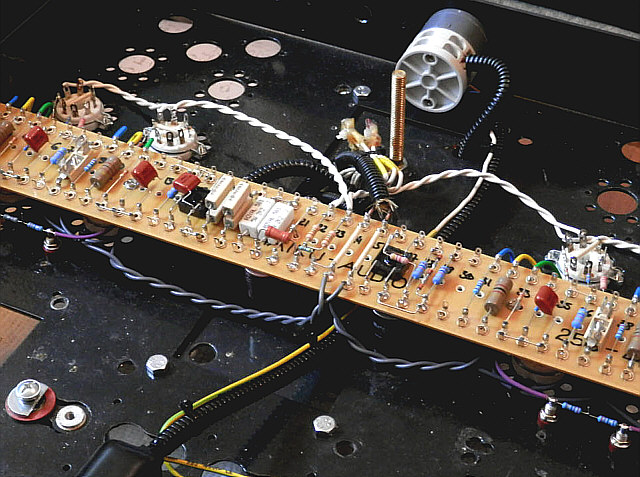
Some components were placed directly on the tube sockets, but this does not hinder access to any point.
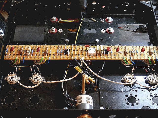
Time for another challenge - resuscitation and installation of output transformers. The only thing I could do for output transformers was cleaning the rosin, repairing terminals and equip it in elegant colored wires and twist the new leads of appropriate length (the original was much too long).
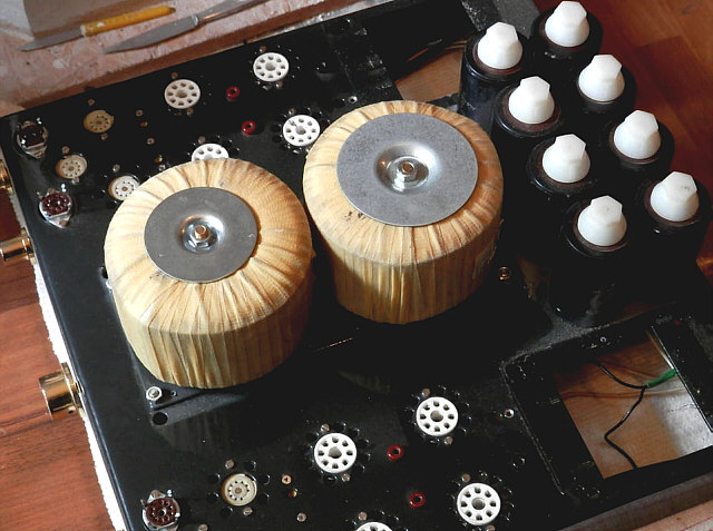
But then I remembered that the owner mentioned, that despite appropriate transformer taps, Ultralinear mode could not be used in this amplifier, because it immediately became unstable. I had an epiphany - after all, the cores of transformers are not connected to anything, and it's asking for trouble. Fortunately, it can be quickly corrected. Here you can see how uneven are drilled mounting holes in the cans for transformers. Of course, the left and right are completely different.
As the secondary windings can be combined in parallel only, I decided to use only one pair of output terminals for each channel.
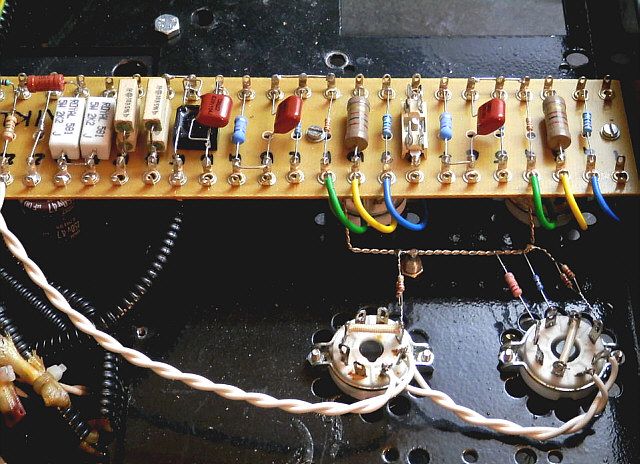
The set of elements was completed by the two coupling capacitors on individual boards.
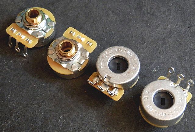
Input selector, this time in the form of atraditional two-section single switch on the PCB. Adjusting the quiescent currents with "mounting potentiometers" has unfortunately been rejected by the customer, who expected to access control components from the outside, without rotating the amplifier upside down.
So I ordered four fairly expensive, but excellent quality large potentiometers, which can not be rotaded "by accident".
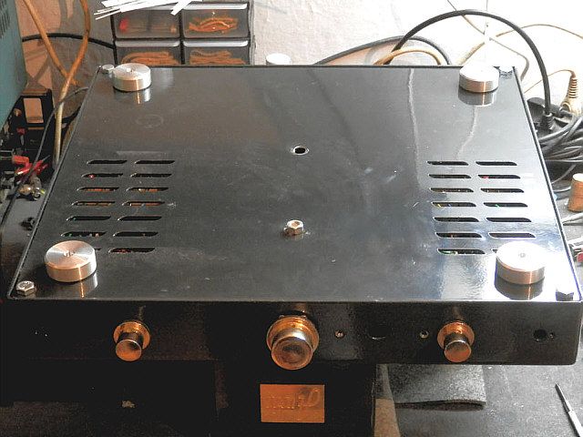
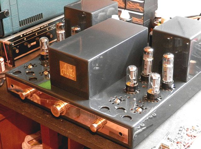
A glance at the whole:
Inside the case schematic diagram and description of the arrangements of the components and voltages at key points appeared in order to facilitate any future servicing.
At the bottom solid feet instead of spikes. However, For the device weighing more than 40kg is a much more practical solution.
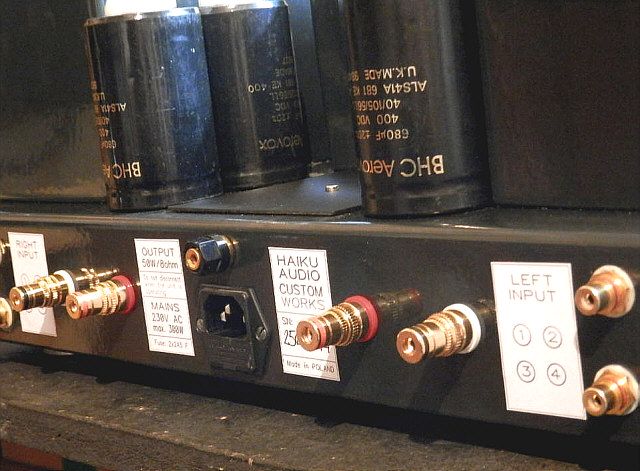
I decided to mask all "curved' holes in the rear with labels. Nothing better not occurred to me.
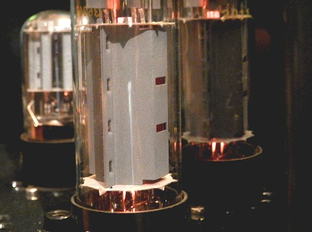
And in this way I got the tube heat  .
.
Now , some technical data:
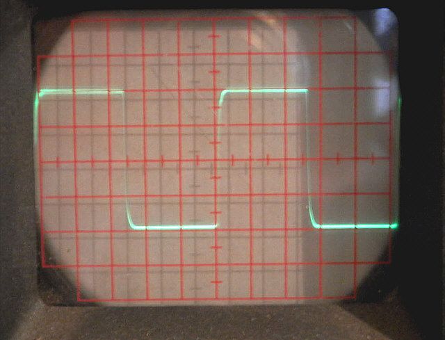
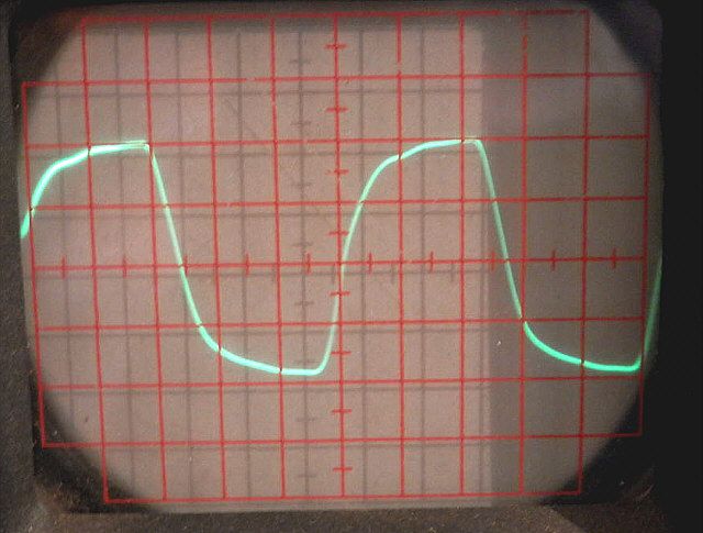
1kHz rectangle is fairly rectangular. I fought valiantly to prevent any excitations and all kinds of ringing.
10kHz rectangle does not look so good, but this is obviously due to bandwidth limitations. And so I'm happy with the result. -3dB at 40 kHz is enough, especially in comparison to 16kHz given by the manufacturer. Before, I have not been able to achieve stability in the whole range of input signal.
Maximum output power with distortion less than 3% is 47W, not so bad for a pair of EL34 in UL system. Lower limit frequency falls below 10Hz, similar to the manufacturer's declaration. All voltages indicated in the diagram agree with the measurement with an accuracy of approximately 5%. Finally, a small comparison.
Before:
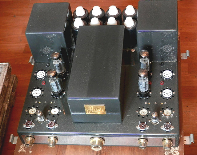
After:
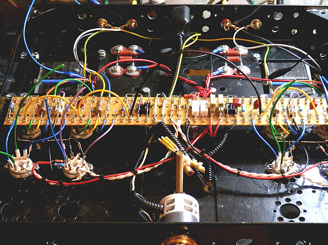
Interior before:

Interior after:
Thank you for your attention and I invite you to follow the thread dedicated to this amplifier on TRIODA Forum at: [Audio-Akustyka Auris, wzmacniacz dla odważnych].
Written by: Piotr Mason (HAIKU-AUDIO),