Mains powered amplifier "5L"
Radioamator, Year III, February 53, No 2
MSc. Czeslaw Klimczewski
In the previous issue of our magazine, a description of the installation of the loudspeaker pickup working in the "push-pull" system was given. The so-called "phase reversal" was obtained in this pickup by means of a vacuum tube, not a transformer. Thanks to not using a transformer and a low-frequency choke, the cost of the amplifying attachment is relatively small and the difficulties in its assembly are also not very high..
Now, developing the scheme of the amplification box, a full 25 watt amplifier will be described, which has a wide range of applications.
As we can see from the schematic diagram shown in Fig. 1 - this amplifier is adapted to be powered with alternating current from the mains with different voltages (from 220 V to 110 V). The first two tubes from the "input" side to the amplifier, i.e. the 6SC7 and 6AC7 tubes - play the role of the so-called "preamplifier", in which the voltages received from microphones, adapter or receiver obtain the appropriate height in order to properly drive the final stage, consisting of a 6SN7 tube reversing the "phase|" and amplification, and two 6L6 tubes operating in push-pull arrangement, providing the necessary power to power the loudspeakers.
The amplifier has three "inputs" M1, M2 and M3. The M1 input sockets are connected to the "s2" control grid of the first triode in the 6SC7 tube (via the P1 slider). The M2 input sockets are similarly connected to the "s1" control grid of the second triode in the same tube (via the P2 potentiometer slider). The anodes of this tube (a1 and a2) are connected together, so that after leaving the tube, the voltages resulting from mixing the already amplified voltages obtained from the M1 and M2 sockets are obtained.
The M3 input sockets are connected through the slider of the potentiometer P3 and the resistor R1 with a resistance of 200 KΩ and the capacitor C1 with a capacity of 1 µF with the anodes (a1 and a2) of the 6SC7 tube connected. Thanks to this, in the anode circuit of this tube, the voltages obtained from the M3 sockets are mixed with the voltages obtained with amplification from the M1 and M2 sockets.
As you can see, the control grid of the 6AC7 vacuum tube is supplied with two amplified voltages (from M1 and M2) and one non-amplified voltage - from M3.
Each input socket is connected by a potentiometer with a resistance of 1 MΩ, thanks to which you can freely adjust the mutual ratios of the received signals.
With three inputs available, you can amplify broadcasts received through one adapter only, one radio receiver, one microphone or two or three microphones simultaneously, or even a combination of microphones, adapter and receiver.
Thanks to these capabilities, the amplifier can be used to transmit various celebrations, games and concerts, in which, apart from the performers, the "announcer" can also take part, it can also be used to "background" music received from a turntable or receiver, and it can also be used to amplify two orchestras located in two different places, alternately, without moving microphones, etc.
It should be remembered, however, that when only one microphone is working, the others, although they are connected to the amplifier, but are not active at the moment - should be disconnected from its circuits by turning the appropriate potentiometers in the direction that turns their full resistance of 1 MΩ into the circuit, thus the slider connects to the grounded base of the amplifier. In this way, no signals from the connected microphones reach the amplifier circuits and do not disturb the amplified ignal with unnecessary conversations, noise and other sounds.
The ratio of the amplified radio broadcasts received by each input can and should be adjusted (by turning the appropriate potentiometer) so that the whole broadcast sounds understandable, nice and vivid. This requires some practice, but it is not so difficult that anyone interested cannot learn it. This kind of manipulation of the potentiometers, which allow you to amplify or attenuate individual parts of the broadcast - is called "mixing".
Radio programs should be amplified by connecting the receiver to the M3 sockets, because then the programs will be reproduced clearer, without distortion. This is explained by the fact that the radio receiver supplies such high voltages with acoustic frequencies that their additional amplification in the first tube may result in overdriving of further tubes of the amplifier, and thus distortions in the reproduced broadcasts. Connect the turntable wires in the same way.
Connecting the receiver (especially low class) to the amplifier is best done through two solid capacitors with a capacity of about 0.1 µF connected (one) to each connecting cable. Such connection will prevent damage to the apparatus if the sockets of the additional loudspeaker in the radio set are connected directly to the anode of the loudspeaker tube and the positive voltage obtained from the anode power supply.
When connecting the turntable cables, make sure that one of them, if grounded, is connected to the amplifier's socket, which is also grounded ("z"). Otherwise, the jacks of the amplifier will be short-circuited and playback of amplified broadcasts will not be achieved..

Fig. 1.
PAfter leaving the 6SC7 tube, the voltages separated on the resistance R3 = 50 kΩ are directed through the capacitor C2 = 50000 pF (50 T) to the control grid (s1) of the next 6AC7 tube. This tube amplifies the received voltages and in turn directs them to the grid of the 6SN7 tube. The control grid (s1) of this tube receives these voltages through the capacitor C7 = 0.1 µF and the potentiometer P5 = 0.5 MΩ, which regulates the overall gain level of the entire amplifier. This potentiometer is called "summing" because it receives (after amplification made in the previous circuits) mixed voltages, resulting from the appropriate adjustment of potentiometers P1, P2 and P3.
To improve the sound of the broadcast, a potentiometer P4 = 100 kΩ connected in a bridge with a capacitor C6 = 10000 pF between the anode of the 6AC7 tube and the grounded base ("ground") of the amplifier was used.
After the output of the 6SN7 tube, the voltages obtained from the "a1" anode control the 1st 6L6 tube of the power stage, while the voltages from the "a2" anode control the 2nd 6L6 tube of this stage. The description of operation and assembly of the power stage together with the phase reversing tube (6SN7) is no different than the description of operation and assembly of the previously mentioned "3L" amplification adapter.
The power supply of this stage is also identical to the power supply of the amplification box, while the preamplifier tubes (6SC7 and 6AC7) obtain the voltages for the anodes and the auxiliary grid reduced at the resistance R18 = 100 kΩ, which together with the electrolytic capacitor C12 = 16 µF creates an additional filter smoothing the voltage received from the power supply. Thanks to this filter, the amplifier works exceptionally cleanly without possible mains hum audible from the speakers.
The amplifier is powered from the alternating current network through a transformer providing the appropriate voltages for the heating of the 5Y3 rectifying tube and the amplifying tubes, as well as the voltage for supplying the anodes of the rectifying tube.
The adjustable resistor commonly known as "entbrummer", similarly to the amplifying attachment, is set once to the minimum hum and does not move it anymore. The other connections are no different from the connections in the amplification box's power supply.
AMPLIFIER ASSEMBLY
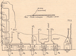
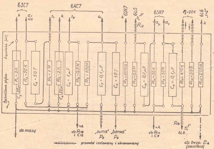
The assembly of the amplifier starts similarly to the amplifying attachment - from the power supply. After its assembly, the ends of the secondary winding (on the mains transformer) intended for the heating of the amplifying tubes are connected first - with the appropriate springs in the tube sockets of all tubes. By connecting the filaments of the tubes to the transformer before making other connections, you can be sure that you will not make a mistake that could expose the tubes to damage. Then, in order to simplify the connections, prepare a bakelite plate, on which, according to the figure 2, the resistors and capacitors listed in the figure must be attached and connected. Having already made the board, the ends of its wires are connected to the appropriate mounting parts of the amplifier. Guided by the schematic diagram in Fig. 1 and the markings on the pedestals seen from the bottom shown in Fig. 5, assembling the amplifier should not present any special difficulties. To facilitate the connection of the amplifier's input circuit, you can use a fragment of the assembly diagram shown in Fig. 3. Also, pay attention to shielding with a metal grid (which must then be grounded by connecting to the amplifier's ground) - all wires, and even if it is successful, also resistors and capacitors located in the control grid circuits of all amplifier tubes. This shielding will remove the harmful effects on these circuits of other circuits, contributing to the stable and correct operation of the amplifier.

Fig. 2.
If a special "braid" made of metal wires cannot be purchased locally, this shielding can be done in such a way that a metal foil made of one unrolled permanent capacitor is wound around a wire in insulation or beads (such as used in electric cookers). This foil, like the sleeve, is terminated at a certain distance from the ends of the wires to protect the wires against a possible short-circuit with it, and thus against immobilizing the amplifier. The ends of the foil are attached to the insulation by wrapping it several times with a thin wire, which is then grounded.
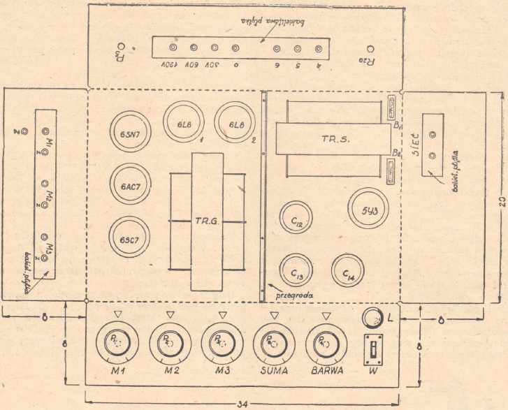
The base of the amplifier can be made using Fig. 4. It is important to position the transformers correctly. These transformers must be positioned as shown in the figure, so that the axes of their cores are perpendicular to each other. This arrangement largely removes the influence of their magnetic fields on each other. In order to further weaken this effect, a partition made of galvanized iron or zinc sheet with a thickness of 1 mm was also used between them. The base of the amplifier is made of the same sheet.
If the base of the amplifier is made of iron sheet, then before mounting the transformers on it, pieces of pressboard or cardboard should be placed under the cores to prevent short circuiting of the cores' lamellae with the metal of the base.

Fig. 3.

Fig. 4.
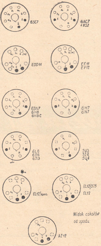
Fig. 5 shows the bottom view of the electron tube sockets. The springs in the tube sockets are also spaced when looking at them from the bottom, i.e. from the inside of the base. The markings of the springs in these sockets correspond to the markings on the schematic diagram (Fig. 1), which makes it very easy to make connections.

Fig. 5.
TTransformers can be purchased on the market or made by yourself. To make the mains transformer TR.S. a core consisting of iron sheets insulated on one side with varnish or shellac with a central column cross-section of about 16 cm2 may be used.
The primary winding should be wound with an enamel wire with a diameter of 0.6 (or 0.5) mm and have 750 turns with taps: for 100V - 350 turns, for 110V - 420 turns, for 120V - 460 turns and for 200V - 700 turns. The full voltage of 220 V is turned on at the ends of the entire winding - (750 turns).
These taps will make it possible to use the energy supply, which has a voltage lower than the nominal one throughout the day. With temporarily reduced voltages in the electrical network - the transformer must not be switched to a lower voltage.
The high-voltage secondary winding should be wound with enameled wire with a diameter of 0.15 (or 1.12) mm. It must have 2600 turns with a tap from the center of the winding, i.e. 1300 turns.
The filament winding of the rectifier tube is wound with enameled wire with a diameter of 1.2 (or 1.0) mm. In the case of using 5Y3, 5Z4, 5U4 or 5C3S (USSR) tubes, it should have 17 turns, and in the case of AZ12 tube filament - 13 turns.
The heating winding of the amplifying tubes should be wound with the same wire and have a number of turns equal to 21.
Some differences between the described transformer and the transformer used in the "3L" tube amplifier are due to the larger number of tubes working in the amplifier.
The speaker transformer TRG (output) should have a core made of plates similarly made as in the previous transformer, except that the cross-section of the central column of the core will be about 12 cm2.
The primary winding of this transformer consists of two sections with the same number of turns. These sections are wound side by side to form two identical windings. They must be wound in the same direction so that both of these sections constitute one winding. The total number of turns is 1800 (900 turns in each section), wound with enameled wire with a diameter of about 0.3 mm. From the center of this winding, i.e. in the place where both sections are connected to each other, a tap is led out.
The first secondary winding wound on both primary sections has 130 turns made of enamel wire with a diameter of 0.8 mm, the next 130 turns wound with a similar wire but with a diameter of about 0.5 mm, and 260 turns - of enameled wire with a diameter of 0.3 mm.
These windings are connected in series to form one secondary winding. From the places where these windings are connected to each other, taps are led outside. So the total number of turns of this winding is 520 - (twice 130 + 260).
At the ends of the first part of the winding (130 turns), voltages with acoustic frequencies of about 30 V are obtained; between the first winding terminal (start) and the second tap (260 turns) - about 60 V; between the same beginning of the winding and the end of the entire winding (520 turns) - about 120 V.
The second secondary winding wound on the first secondary winding has 85 turns with taps for 26 and 42 turns. The enamel wire used to wind this winding should have a diameter of about 0.15 mm.
This winding provides the low voltage needed to power dynamic loudspeakers without transformers in the cabinet.
Note that when winding the described transformers, it is necessary to keep the same winding directions in all windings.
Finally, we provide a list of assembly parts.
- 1 amplifier base made of galvanized iron or zinc sheet, 1 mm thick. Base dimensions: 34 cm x 20 cm x 8 cm. This base should have holes made according to the dimensions of the tube bases and the spacing of individual components. It is also desirable that it has a closed bottom and a cover covering the entire amplifier. This cover should be perforated at the back so that the released heat can escape to the outside.
- 1 mains transformer. Gradual mains voltages from 220 V to 110 V. Anode winding: 2 x 360 V (or 350 V) with a load of 150 mA. Rectifier tube filament winding: 6.3V (or 5V)/3Amp. Heater winding of the amplifying tubes: 6.3 V/4 - 5 Amp.
- 1 speaker transformer (output). It must be adapted to work in push-pull mode with 6L6 tubes and have the power to turn on a 25 watt load. On the secondary side, it must provide voltages of 30, 60, 120V and (if possible) voltages for direct powering of dynamic loudspeakers.
- 1 tube 6SC7 or EDD11, 6N7, 6H8C
- 1 tube 6AC7 or 1852, EF11, EF12
- 1 tube 6SN7 or 6H7, 6N8S, 6N7
- 2 tubes 6L6 or 6∏6, 6∏3, EL12/Spec, EL12/375, (or EL12 - lower oputput power)
- 1 rectifying tube type 5Y3 lub 5Z4, 5U4, 5C4S, AZ12
- 3 potentiometers 1 MΩ - P1, P2, P3
- 1 potentiometer 100 kΩ - P4
- 1 potentiometer 20 kΩ - P5
- 1 potentiometer 0,5 MΩ - Pa
- Resistors
- R1 = 200 kΩ/1W
- R2 = 3000 Ω/1-2W
- R3 = 50 kΩ/1W
- R4 = 1 MΩ/1W
- R5 = 3 kΩ/1-3W
- R6 = 0,5 MΩ/1W
- R7 = 100 kΩ/1W
- R8 = 1500 Ω/2W
- R9 = R10 = 3 kΩ/1W
- R11 = 5000 Ω/2W
- R12 = 450 kΩ/1W
- R13 = 30 kΩ/1W
- R14 = 0,5 MΩ/1W
- R15 = 250 Ω/15W (for EL 12/ Sp. - about 90 Ω)
- R16 = R17 = 1000 Ω/1W
- R18 = 100 kΩ/2W
- R19 = 2000 Ω/2W
- R20 = 50 Ω - adjustable ("entbrummer")
- RF = 3000 Ω/około 20W - wire
- Capacitors:
- C1 = 1µF/1500V (ew. 750 V)
- C2 = 50000 pF/1500V
- C3 = 25 µF/30V - electrolytic
- C4 = 50 µF/30V - electrolytic
- C5 = 1 µF/1500V (or 750 V)
- C6 = 10000 pF/1500V
- C7 = 0,1 µF/1500V
- C8 = 1 µF/1500V (eor 750V)
- C9 = C10 = 0,1 µF/1500V
- C11 = 1 µF/1500V (or 750 V)
- C12 = 16 µF/550V - electrolytic
- C13 = C14 = 32 µF/550V - electrolytic
- C15 = C16 = 10000 pF/3000V
- 1 mains switch, instant
- 1 socket for a signal bulb
- 1 signaling bulb 6.3V/0.3A
- 6 tube sockets suitable for the tubes used
- 16 sockets
- 2 holders for glass fuses
- 2 glass tubular fuses for 1A loads
Bakelite plates, mounting wire with a minimum diameter of 0.8 mm in plastic or rubber insulation, cable shielding, screws, nuts, tin for soldering, rosin (dissolved in spirit), etc.


