Radio amateur and amateur radio operator of Poland, Year 22, October 1972, No. 10.
CONTENT.
- FROM THE COUNTRY AND ABROAD.
- Trade mission of the US radio industry in Poland (245)
- XVII General Meeting of the International Scientific Radio Union (URSI) (245)
- Radiotelephone in the range 450 - 470 MHz (245)
- New measuring instruments from CSRS (245)
- Consumer electronics at the Poznań International Fair (246)
- Trade mission of the US radio industry in Poland (245)
- TV.
- General overview of the main components in color television receivers - Part I - Marek Tarnowski (249)
- ELECTROACOUSTICS.
- Stereo acoustic set "Ziphona S" - Vol. II and last - MSc. Jerzy Serafin (250)
- Preamplifier for ZK 140 and ZK 145 tape recorders - Janusz Gajewicz (262)
- AMATEUR RADIO COMMUNICATION.
- Transistor receiver for fox hunting "FOX" - Ludwig Dzida - SP3CAR (253)
- MEASUREMENT TECHNIQUE.
- Pulse oscilloscope - Zbigniew Waluś (255)
- DO YOU KNOW THAT... (263)
- MISCELLANEOUS.
- Practical workshop tips - Juliusz Kabarowski (264)
- POLISH SHORT WAVE (265)
- AMATORY RADIO IN LOK (268)
FROM THE COUNTRY AND ABROAD.
- Trade mission of the US radio industry in Poland.
On September 18-23, a special trade mission composed of presidents and directors of 12 of the most important US radio companies visited Warsaw to establish trade contacts and explore the possibility of supplying our market with products of such companies as RCA, COLLINS-RADIO, GENERAL DATA Comm, Industries, ITT, MAGNAVOX, GENERAL DYNAMICS Corporation. - XVII General Meeting of the International Scientific Radio Union (URSI).
On September 21-29 this year, under the patronage of Prime Minister Piotr Jaroszewicz, the General Meeting of the International Union Radio Scientifique Internationale was held in Warsaw with the participation of over 600 scientists from 31 countries. - Radiotelephone in the range 450 - 470 MHz.
The increasing demand for frequencies for various mobile services has forced manufacturers to move to the decimeter ranges.
An example of a solution of this type of equipment is the PYE "Pocketfone" radio (Fig.). - New measuring instruments by CSRS.
The Czechoslovakian company METRA-BLANSKO, known for its high-quality production of measuring instruments, has developed a series of modern measuring instruments for various service and laboratory applications. An example of such a solution is the PU 160 type instrument designed for measuring voltages and resistances with high input resistance (Fig.).
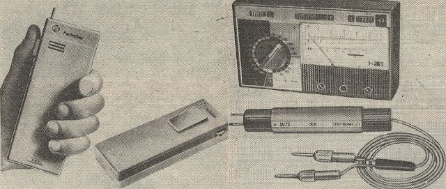
"Pocketfone" radiotelephone (left) and PU 160 type electronic device (right).
- Consumer electronics at the Poznań International Fair.
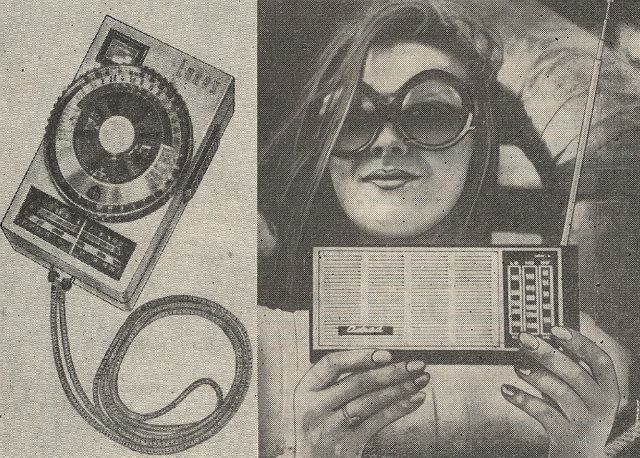
Light meter and transistor receiver equipped with internal ferrite antenna and telescopic antenna.
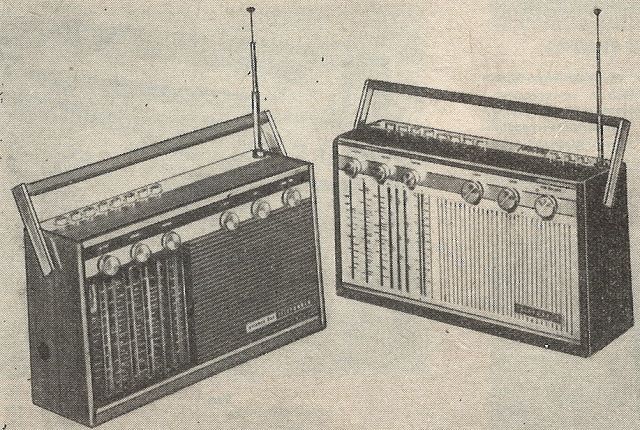
Advanced multi-band radio receivers.
General overview of the main components in color television receivers - Part I.
Due to the differences in different designs of color television receivers, I limit myself here only to a general description of components used in receivers of European production.
The layout of the color television program receiver is much more complex than that of the black and white television receiver. A number of assemblies have increased tolerance, which affects a very complex technological process. In this article, intended for readers who know the issues of YOU black and white, only those components of color television receivers will be described, which differ significantly from those previously used in black and white television receivers.
Stereo acoustic set "ZIPHONA-S" - Part II and last.
Construction.
The acoustic amplifier and the "Ziphon" turntable are placed in a 400 x 300 x 100 mm housing made of plywood, which is then veneered. The sides of the casing (10 mm thick) together with the bottom wall (8 mm thick) constitute one unit, while the top plate for the turntable is made of 12 mm plywood and screwed to the casing with four wood screws. Cut the hole for mounting the "Ziphon" turntable according to the manufacturer's leaflet.
All functional blocks of the acoustic amplifier are attached to the housing of the device.
The preamplifier (both channels) was assembled on a printed circuit board (Fig. 5), the general view of which is shown in Fig. 6.
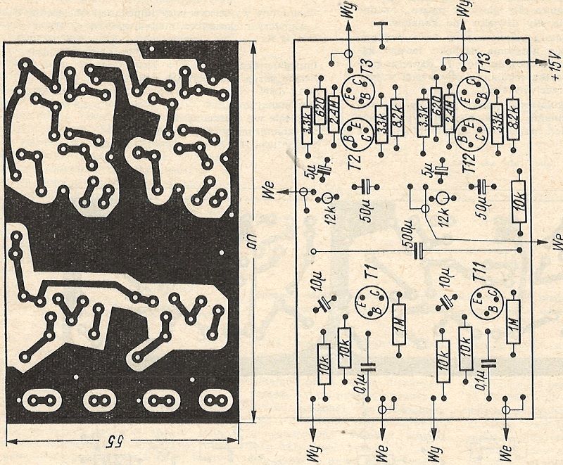
Fig. 5. Printed connections and arrangement of elements on the preamplifier board.
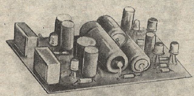
Fig. 6. General view of the preamplifier.
The discussed units were attached to the front panel of the housing, to which the front panel with inscriptions engraved on it was screwed with four screws. The front plate, the main dimensions of which are given in Fig. 7, is made of a semi-hard aluminum sheet with a thickness of 1.8 mm.
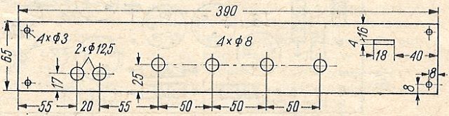
Fig. 7. Turntable front plate - dimensions.
The end steps and the power supply (Fig. 8 and Fig. 9) were attached to the bottom of the housing with countersunk screws. The elements of the power supply, due to a certain freedom in their selection, can be assembled in various ways. An example of a solution is presented in Fig. 10.
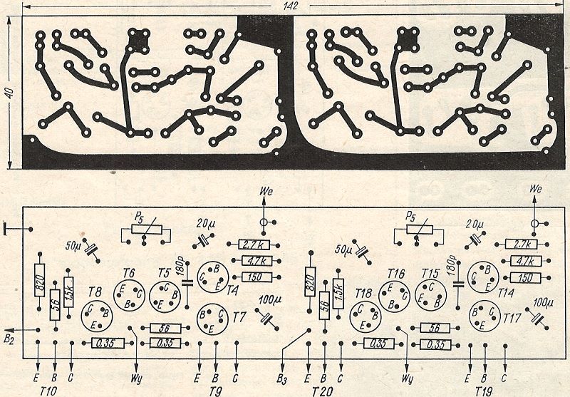
Fig. 8. Printed connections and arrangement of elements on the power amplifier board.
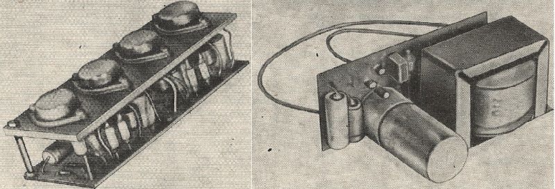
Fig. 9. General view of the power amplifier (left).
Fig. 10. General view of the AC adapter (example solution) (on the right).
Fig. 11 shows the arrangement of individual units and elements inside the turntable housing.
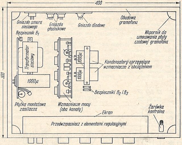
Fig. 11. Placement of components and elements of a stereo phono amplifier with a power supply inside the housing (top view).
The loudspeaker housings with dimensions of 800 x 300 x 160mm are made of 8mm plywood. Only the front panel of the column, the shape and dimensions of which are shown in Fig. 12, was made of 12mm plywood.
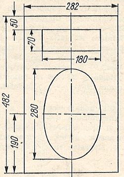
Fig. 12. Front panel of the loudspeaker - dimensions.
The construction of the loudspeaker housing is reinforced with stiffening strips with a cross-section of 20 x 20mm; they serve simultaneously to fasten the faceplate and rear panel to the housing. The speaker sets are connected to the amplifier by 4m long cables (e.g. lighting cord) with appropriate plugs..
A general view of the "Ziphona-S" turntable with loudspeakers is presented in part I of the article - No. 9/72, page 221.
Transistor receiver for fox hunting "FOX".
The receiver made by me is a 9 - transistor superheterodyne with a typical arrangement. In this type of receivers, capacitive tuning of the heterodyne is most often used. I used induction; it gives the same effects, and in the mechanical solution it is much simpler.
Pulse oscilloscope.
The oscilloscope described here is an instrument with a simplified structure that can be made in an amateur environment. It allows you to track pulse waveforms from 0.1 to 50,000 microseconds with an amplitude from 100mV to 600V, as well as periodic curves of processes in the frequency range from 20Hz to 10MHz, measure the pulse amplitude length, compare the phases of two observed waveforms, compare the frequency using Lissajous figures, and with an appropriately adapted signal generator - the study of resonance curves of bandpass filters and circuits.
Preamplifier for ZK 140 and ZK 145 tape recorders.
The described preamplifier is used to amplify the voltages obtained directly from the tape head. By connecting the preamplifier output to the input of an additional amplifier or headphones, for example, you can play stereo recordings from tapes or make synchronous recording. For example, we have recorded background music on track 1-2, and we want to save the accompanying text on track 3-4. For this purpose, switch 3-4 on the track on which the recording will take place. Set the tape recorder in the "Record" position. After switching on the drive, the background music from track 1-2 amplifies our preamplifier. So we can hear it through headphones or a loudspeaker, and on track 3-4 we make a synchronous recording. We can play this complex record by using a tape recorder amplifier and playing two tracks simultaneously; you can of course play each track separately.
The diagram of the preamplifier is shown in Fig. 1. The system consists of a three-stage amplifier with direct coupling between the stages and a supply voltage filter equipped with a T4 transistor. The frequency correction was adjusted to the tape speed 9.53 cm / s. The range of reproduced frequencies: 40Hz - 14kHz.
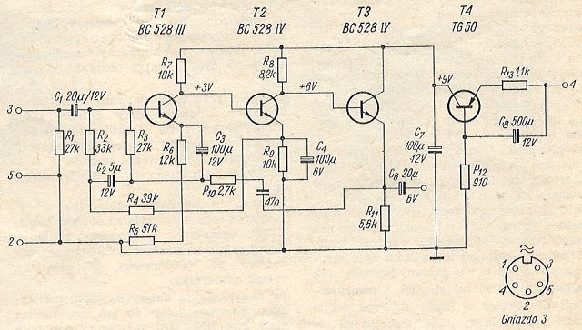
Fig. 1. Schematic diagram of the preamplifier.
The preamplifier is assembled on the printed circuit board shown in Fig. 2.
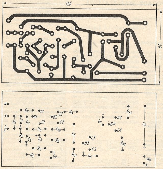
Fig. 2. The printed circuit board and the arrangement of elements on the board.
The whole is connected to the tape recorder using a five-pin plug attached to the tape recorder's socket. The cable length is approximately 0.7 m. The amplified signal is received from the socket located in the preamplifier housing. After adjustment, the whole should be placed in a shielded box.
Practical workshop tips.
Mutual positioning of inductive elements in electroacoustic structures.
Much trouble in the construction of RF amplifiers, radio receivers, tape recorders, etc. is caused to less experienced radio amateurs by harmful inductive couplings occurring between improperly positioned transformers, chokes, motors or other elements generating a scattered magnetic field around them..
When planning the arrangement of these components on the mounting plate, radio amateurs are guided by the general rules of mutual positioning of inductive elements, described in the professional literature, and consisting mainly in the maximum distance between these elements and the perpendicular arrangement of transformer cores, chokes, coils, etc. to each other. Magnetic shielding of these components is unlikely to be an option due to the difficulty of implementation and low efficiency.
After assembling and starting the device, it often turns out that the theoretical calculations do not work well in practice and the location of some components requires correction, because despite the observance of all the rules for the arrangement of inductive elements, there is an unpleasant mains hum. Excessive distance between inductive elements may also cause disturbances induced in connecting cables that are too long, and also leads to an unnecessary increase in the dimensions of the device. Since the mutual interaction of inductive elements is determined by not one, but the whole set of factors simultaneously, the optimal location of these elements on the chassis is achieved only after many attempts and modifications to the assembly.
All these labor-intensive and often spoiling the final effect of corrections can be avoided by using the method of acoustic positioning of inductive elements in relation to each other, described later in this article. It consists in supplying one of these components, e.g. a transformer, during the design of the assembly diagram, with voltage with an acoustic frequency and listening to the low frequency signal. possibly induced in the winding of an adjacent component, e.g. a choke. This method is illustrated in Fig. 1, which shows schematically the electrical system most often used by designers when solving the problem of the mutual positioning of the supply (mains) transformer and the output (loudspeaker) transformer..
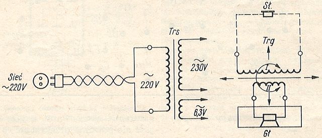
Fig. 1. Diagram of one of the listening circuits when determining the mutual position of the mains and loudspeaker transformer.
We put both transformers temporarily on the chassis. After securing the ends of the secondary (anode and glow) windings of the mains transformer against accidental short-circuit or the possibility of electric shock, connect the primary (i.e. mains) winding of this transformer, via an insulated two-wire cable, to a mains socket. To the secondary (low-resistance) winding of the output (speaker) transformer, connect a loudspeaker that reproduces low tones well (in the housing or on the screen!), Preferably the one that is to work in a given device.
By changing the distance between both transformers and the angle of mutual positioning of the cores, we aim to achieve the disappearance of the 50Hz tone audible in the loudspeaker. Such a location of the transformers, where the loudspeaker is completely silent, despite the small distance between them, is the optimal setting, which we mark by outlining the contours of both transformers directly on the chassis or on paper underlay. Instead of a loudspeaker, we can use to listen to the hum induced in the output transformer of radio headphones - connected to the primary (high-resistance) winding of the transformer. However, taking into account the fact that average headphones do not reproduce low tones well and in the case of powering the mains transformer with a current of 50 Hz, such a test may turn out to be unreliable.
We can also supply the mains transformer with a signal with a frequency greater than 50Hz, obtained from any acoustic generator with a sufficiently high power. As a generator you can successfully use any low frequency amplifier for this purpose. (e.g. from a radio) by introducing positive feedback to it with an appropriate frequency response.
The monitoring of the signal induced in the sub-assembly adjacent to the powered element can also be performed via a low-frequency amplifier, e.g. a signal-tracer, where, in this case, transistor amplifiers insensitive to external interference fields are particularly useful. The low-resistance windings should be connected to the amplifier input with short or shielded wires.
The described method can be used for the mutual positioning of chokes in rectifier filters in relation to the network transformer, two output transformers in two-channel amplifiers (e.g. stereo) in relation to each other, transformers, chokes and playback heads or universal ones in relation to the motor in tape recorders and turntables.
The condition for the success of the described method is the principle that the low frequency signal strength connected to the winding of one of the inductive elements was approximately equal to the power of alternating current flowing in the windings of this element during normal operation of the designed device, and when listening to the signal induced in adjacent inductive components - it is important to properly match the loudspeaker or headphones to the impedance of the tested winding.
Replacement of the selenium diode SPS-2-40-05 with the germanium diode DOG31 in "Neptun 1741" TV sets and similar.
The SPS-2-40-05 selenium diode, marked in the diagram as D9, works in the keyed automation system of the "Neptun" 17 inch TV receiver. Damage (puncture) of this diode makes it impossible to adjust the image contrast.
The difficulties in acquiring a diode of this type prompted me to try to replace it with a germanium spiked diode. It turned out that the DOG31 germanium diode works perfectly in this place. Some DOG31 units, however, may require increasing the forward bias voltage by reducing the value of the R149 resistor from 16MΩ to 10MΩ..
Polish amateur radio.
Radio amateurism at LOK.
Publishing House of Communication and Communications.
")
")
")
")
")